background image

31

Meter Operations

 
3.4.3

3.4.3

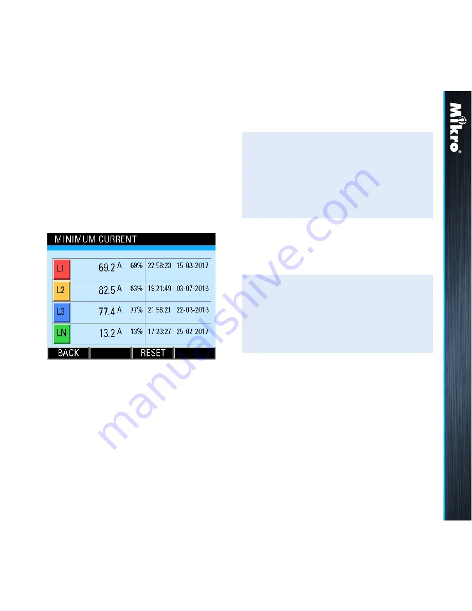
MiniMuM CurrEnT

The Minimum current page shows the recorded 

minimum true RMS current of each phase and 

where applicable, neutral with the corresponding 

time and date since the last reset as shown in 

Fig 35:

Fig 35 : Minimum Current page

The time and date records are displayed in the 

hour:minute:second day-month-year format.

TouCH BuTTon funCTions:

• to reset the recorded minimum current values 

to zero, touch the reset (f3) button.

• otherwise, touch the bacK (f1) button to 

return to the current sub-menu.

In clearing the recorded values, the user

will be prompted with a clear logged Data? 

confirmation.

When these recorded values are cleared, the 

corresponding time and date records are also 

cleared to the default 00:00:00 00-00-2000.

TouCH BuTTon funCTions:

• to confirm clearing the recorded values, touch 

the yes (f4) button.

• otherwise, touch the no (f2) button.

Содержание DPM680

Страница 1: ......

Страница 2: ...r use the device in accordance with the instruction may cause harmful interference This does not however guarantee that interference will not occur in any installation In case of interference the user...

Страница 3: ...3 7 Sequence Voltages 24 3 3 8 Voltage Harmonics 25 Table of content 3 3 9 Voltage Harmonics Table 26 3 3 10Voltage Waveform 27 3 4 CURRENT sub menu 28 3 4 1 Phase Current 29 3 4 2 Maximum Current 30...

Страница 4: ...only for DPM680 60 3 8 2 2 Modbus 61 3 8 2 3 View Network Details only for DPM680 62 3 8 3 System Settings 63 3 8 3 1 Version 63 3 8 3 2 Date Time 64 3 8 3 3 Change Device Password 65 3 8 3 4 Factory...

Страница 5: ...nt harmonic spectrums up to the 32nd order Introduction 1 1 1 For SCADA and remote monitoring this power meter also comes with Modbus RTU connectivity Modbus TCP IP connectivity only for DPM680 Built...

Страница 6: ...Currents Current Harmonics Current THD Current Waveform Current Harmonics Table PF and Frequency Power Factor PF Displacement PF DPF Max Min Inductive PF Max Min Capacitive PF Max Min Frequency Active...

Страница 7: ...Reactive Power Apparent Power Total Power Power Demand Maximum Power Demand Maximum Active Power Minimum Active Power Maximum Reactive Power Minimum Reactive Power Maximum Apparent Power Minimum Appa...

Страница 8: ...x you should find the following items shown in Table 1 1 3 Parts of the Power Meter Fig 2 shows the outline dimension of the power meter Table 1 Parts list 1 2 3 4 5 6 DPM680 B power meter Retainer cl...

Страница 9: ...Metering voltage connection Current input Metering current connection RS 485 port RS 485 connection for Modbus RTU RJ45 port LAN connection for Modbus TCP IP webserver only for DPM680 Retainer clip Re...

Страница 10: ...he following safety precautions before and during the installation of the power meter Only competent and trained personnel should install this device Use appropriate personal protective gloves glasses...

Страница 11: ...22 Please make sure the power to the voltage metering input is totally removed Shunt any unused metering voltage input to the N input connection Fig 5 Metering voltage input detachable terminal block...

Страница 12: ...ln Ln L3 L2 L1 Ln 90 415 V AC 100 300 V DC AUX RS 485 Modbus RTU LOAD Ethernet Only for DPM 680 L3 L2 L1 RS 485 Modbus RTU Ethernet Only for DPM 680 S2 S1 S2 S1 S2 S1 l3 GND l2 l1 S2 S1 ln Ln L3 L2 L1...

Страница 13: ...d wire size is AWG 16 20 The recommended fuse part no is LVSP5 from Littelfuse Please note that without this fuse the meter installation is only rated at CAT II For CAT II installations an adequate ci...

Страница 14: ...proper connection is made Avoid running the cable near sources of electrical noise The network cable shield should be grounded at only ONE end Fig 12 Modbus RTU connections 2 3 Meter Setup Before com...

Страница 15: ...mum and minimum inductive power factor see section 3 5 4 maximum and minimum capacitive power factor see section 3 5 5 maximum and minimum frequency see section 3 5 6 maximum power demand see section...

Страница 16: ...ter In the instance of the above default subnet mask only devices e g PC or router etc with IP addresses that begin with 192 168 28 can communicate with the meter For direct PC connection the IP addre...

Страница 17: ...display and 4 touch buttons labelled F1 F2 F3 and F4 as shown in Fig 15 To touch the button simply place a finger on the square below the labels corresponding to the menu item at the bottom of the dis...

Страница 18: ...han 5 minutes the display will default to the OVERVIEW page Fig 16 MAIN MENU Meter Operations 3 1 3 2 3 2 Password Authentication For authentication in the parameter setting operations the user may be...

Страница 19: ...eter Operations 3 2 Touch BUTTON functions to increase the number touch the UP F2 button to decrease the number touch the DOWN F3 button to select the next active field to change touch the NEXT F1 but...

Страница 20: ...ouch the ENTER F4 button to return to the MAIN MENU touch the BACK F1 button 3 3 VOLTAGE sub menu The VOLTAGE sub menu allows the selection of voltage parameter pages as shown in Fig 18 and its contin...

Страница 21: ...ine Voltage page touch the PEAK F2 button to jump to the Phase Voltage page touch the PHASE F3 button to jump to the Voltage Waveform page touch the WAVE F4 button otherwise touch the BACK F1 button t...

Страница 22: ...date records are also cleared to the default 00 00 00 00 00 2000 3 3 4 MINIMUM PHASE VOLTAGE The Minimum Phase Voltage page shows the recorded minimum true RMS phase voltage with the corresponding tim...

Страница 23: ...reset as shown in Fig 24 Fig 24 Maximum Line Voltage page Touch BUTTON functions to reset the recorded minimum voltage values to zero touch the RESET F3 button otherwise touch the BACK F1 button to re...

Страница 24: ...25 Fig 25 Minimum Line Voltage page The time and date records are displayed in the hour minute second day month year format Touch BUTTON functions to reset the recorded minimum voltage values to zero...

Страница 25: ...turn to the VOLTAGE sub menu 3 3 8 Voltage Harmonics The Voltage Harmonics page shows the voltage harmonics spectrum and the voltage Total Harmonics Distortion THD of each phase Upon entering this par...

Страница 26: ...ayed as shown in Fig 28 Fig 28 Voltage THD parameter page Touch BUTTON functions to return to the Voltage Harmonics page touch the BACK F4 button Touch BUTTON functions to alternate between the odd an...

Страница 27: ...or F4 one more time The RED YELLOW and BLUE traces show the voltage waveform of phases L1 L2 and L3 respectively 3 3 10 Voltage Waveform The Voltage Waveform page shows the phase voltage waveform of a...

Страница 28: ...change the trigger source among the 3 phases touch the TRIG F1 button to zoom out the voltage display scale touch the F2 button to zoom in the voltage display scale touch the F3 button otherwise touch...

Страница 29: ...ameter item is highlighted within a dashed rectangular box and a RED dot to its left To confirm this selection touch the ENTER F4 button to return to the MAIN MENU touch the BACK F1 button 3 4 1 Phase...

Страница 30: ...Logged Data confirmation When these recorded values are cleared the corresponding time and date records are also cleared to the default 00 00 00 00 00 2000 Touch BUTTON functions to confirm clearing...

Страница 31: ...month year format Touch BUTTON functions to reset the recorded minimum current values to zero touch the RESET F3 button otherwise touch the BACK F1 button to return to the CURRENT sub menu In clearing...

Страница 32: ...Please see section B 1 in Appendix B for details Fig 36 Current Demand page Touch BUTTON functions to jump to the Current Demand Setup page as shown in Fig 37 touch the SET F2 button to jump to the Ma...

Страница 33: ...le number multiples of the number of sub intervals and the sub interval period must be longer than 15 secs to select the next field to change touch the NEXT F4 button and repeat the above 2 steps to s...

Страница 34: ...uch the NO F2 button In clearing the recorded values the user will be prompted with a Clear Logged Data confirmation When these recorded values are cleared the corresponding time and date records are...

Страница 35: ...content will NOT be displayed Fig 40 Current Harmonics page The harmonics content is displayed as a percentage of the fundamental phase current Please see section B 2 in Appendix B for more details F...

Страница 36: ...rmonics spectrum display touch the EVEN F2 or ODD F2 button to display the spectrum of the next phase touch the NEXT F3 button to jump to the THD parameter page as shown in Fig 41 touch the THD F1 but...

Страница 37: ...e display zoom levels correspond to a maximum range of approximately 20 40 and 80 of the rated rms metering current input 5A The time capture span is fixed at approximately 65 msec Touch BUTTON functi...

Страница 38: ...rectangular box and a RED dot to its left To confirm this selection touch the ENTER F4 button to return to the MAIN MENU touch the BACK F1 button Touch BUTTON functions to change the trigger source am...

Страница 39: ...ton otherwise touch the BACK F1 button to return to the PF FREQUENCY sub menu 3 5 2 Power Factor PF The Power Factor page shows the total power factor for each phase as well as the overall total power...

Страница 40: ...hase as shown in Fig 47 The displacement power factor is derived from the fundamental component of the phase voltage current and fundamental active power Please see section B 4 in Appendix B for more...

Страница 41: ...PF values to zero touch the RESET F3 button otherwise touch the BACK F1 button to return to the PF FREQUENCY sub menu Touch BUTTON functions to reset the recorded maximum and minimum PF values to zero...

Страница 42: ...ed values touch the YES F4 button otherwise touch the NO F2 button Touch BUTTON functions to confirm clearing the recorded values touch the YES F4 button otherwise touch the NO F2 button 3 5 6 MAX MIN...

Страница 43: ...ect the parameter page of interest touch either the UP F2 or DOWN F3 button until the parameter item is highlighted within a dashed rectangular box and a RED dot to its left To confirm this selection...

Страница 44: ...e touch the P F2 button to jump to the Total Power page touch the ALL F3 button to jump to the Apparent Power page touch the S F4 button otherwise touch the BACK F1 button to return to the POWER sub m...

Страница 45: ...s the nett apparent power for each phase as well as the total nett apparent power as shown in Fig 55 Fig 55 Apparent Power page Touch BUTTON functions to jump to the Active Power page touch the P F2 b...

Страница 46: ...the SET F2 button to jump to the Maximum Power Demand page touch the MAX F4 button otherwise touch the BACK F1 button to return to the POWER sub menu Touch BUTTON functions to input new settings touc...

Страница 47: ...and the sub interval period must be longer than 15 sec Note When the Demand Interval is changed the sub intervals defaults to 2 This can however be changed separately when the NEXT F4 button is touche...

Страница 48: ...the NO F2 button In clearing the recorded values the user will be prompted with a Clear Logged Data confirmation 3 6 7 MAXIMUMACTIVE POWER The Maximum Active Power page shows the recorded maximum act...

Страница 49: ...aring the recorded values the user will be prompted with a Clear Logged Data confirmation 3 6 8 MINIMUMACTIVE POWER The Minimum Active Power page shows the recorded minimum active power for each phase...

Страница 50: ...g 62 Maximum Reactive Power page Touch BUTTON functions to reset the recorded maximum reactive power values to zero touch the RESET F3 button otherwise touch the BACK F1 button to return to the POWER...

Страница 51: ...Fig 63 Fig 63 Minimum Reactive Power page Touch BUTTON functions to reset the recorded minimum reactive power values to zero touch the RESET F3 button otherwise touch the BACK F1 button to return to t...

Страница 52: ...ed values the user will be prompted with a Clear Logged Data confirmation The time and date records are displayed in the hour minute second day month year format When these recorded values are cleared...

Страница 53: ...d with a Clear Logged Data confirmation The time and date records are displayed in the hour minute second day month year format When these recorded values are cleared the corresponding time and date r...

Страница 54: ...numbers touch the F2 button to view the digits on the left of the displayed numbers touch the F3 button Touch BUTTON functions to select the parameter page of interest touch either the UP F2 or DOWN F...

Страница 55: ...mplete due to the limited display width Use the and buttons to view the complete values Touch BUTTON functions to view the digits on the right of the displayed numbers touch the F2 button to view the...

Страница 56: ...tton to return to the ENERGY sub menu The displayed values may be incomplete due to the limited display width Use the and buttons to view the complete values Touch BUTTON functions to view the digits...

Страница 57: ...5 Reset Energy Counters When the Reset Energy Counter page is selected the user will be prompted with a Clear All Registers confirmation 3 8 SETTING sub menu The SETTING sub menu allows the selection...

Страница 58: ...from 60 V to 300V full scale Note The VT secondary voltage must be lower than the VT primary voltage Touch BUTTON functions to input new settings touch the SET F4 button otherwise touch the BACK F1 b...

Страница 59: ...ing the settings touch the NO F3 button to return to the SETTING sub menu otherwise touch the YES F2 button to save the settings and the user will be prompted for password authentication as in section...

Страница 60: ...e the number or toggle the field touch the UP F2 button to decrease the number or toggle the field touch the DOWN F3 button to select the next field to change touch the NEXT F4 button and repeat the a...

Страница 61: ...the new IP settings to take effect Touch BUTTON functions to input new settings touch the SET F4 button otherwise touch the BACK F1 button to return to the Communication Settings page only for DPM680...

Страница 62: ...n Even Odd No No 1 1 2 1 Parity Stop Table 3 RS 485 data format Touch BUTTON functions to abort saving the settings touch the NO F3 button to return to the Modbus sub page otherwise touch the YES F2 b...

Страница 63: ...a dashed rectangular box and a RED dot to its left To confirm this selection touch the ENTER F4 button to return to the SETTING sub menu touch the BACK F1 button 3 8 3 1 Version The Version sub page d...

Страница 64: ...ton to return to the System Settings page Touch BUTTON functions to increase the number touch the UP F2 button to decrease the number touch the DOWN F3 button to select the next field to change touch...

Страница 65: ...sub page Touch BUTTON functions to abort the saving operation and return to the System Settings page touch the BACK F1 button otherwise touch the SET F4 button to input the password The UTC Time is t...

Страница 66: ...process has to be repeated unless aborted by touching the BACK F1 button If the password is correct it will be saved and the display will return to the System Settings page The password for this purpo...

Страница 67: ...ay Setting sub page Meter Operations 3 8 3 5 The user will be prompted to confirm the saving of settings In the input mode the UP F2 and DOWN F3 buttons will become active and the background colour of...

Страница 68: ...ays the following parameters Note Please ensure the LAN is properly connected to the meter and the TCP IP setting is properly configured both at the meter and the client and or router line voltage bet...

Страница 69: ...d Current webpage display By clicking on the links at the bottom of the webpage the browser will download the corresponding webpage Clicking on the Voltage and Current link will reload this webpage We...

Страница 70: ...lacement and total power factor all phases overall total power factor nominal active reactive apparent power demand maximum peak active reactive and apparent power demand nominal thermal current deman...

Страница 71: ...71 Fig 83 Energy and Power webpage display Webpage Operations 4 2...

Страница 72: ...this webpage the user is allowed to modify the following displayed parameters VT primary voltage VT secondary voltage CT primary current power demand interval power demand sub interval blocks thermal...

Страница 73: ...73 Fig 84 Energy and Power webpage display Webpage Operations 4 3...

Страница 74: ...d 50 000V the VT secondary voltage is between 60V and 300V AND it is lower than the VT primary voltage the CT primary current is between 5A and 50 000A the interval for both thermal current demand and...

Страница 75: ...s and their respective addresses are similar for both protocols and they are listed in the DPM680 Modbus Communication Manual which can be downloaded from the www itmikro com website The Modbus regist...

Страница 76: ...phase order and polarity Meter unable to communicate with remote terminal Possible Causes Possible Solution No power from the meter control power supply to the meter Incorrect setting Improper termin...

Страница 77: ...ows the list of measurement parameters and their associated limits and resolution It also shows the display communication environmental and mechanical attributes of the meter including standards compl...

Страница 78: ...78 Table A 1 Specification list Appendix A...

Страница 79: ...79 Table A 1 Specification list Appendix A...

Страница 80: ...80 Table A 1 Specification list Appendix A...

Страница 81: ...erage of the n consecutive sub interval quantity averages over the demand interval i e qs n The demand quantity is therefore updated at the expiry of each sub interval In the example shown in the figu...

Страница 82: ...are abstract quantities resolved from the phase voltages and currents They describe the degree and nature of imbalance and phase reversal Any 3 phase system can be resolved into 3 balanced 3 phase co...

Страница 83: ...components of the voltage current and active power i e Displacement power factor Fundamental active power Fundamental RMS voltage x Fundamental RMS current B 5 Apparent Power Calculation For individu...

Страница 84: ......

Отзывы: