


MCAC-ATSM-2013-11 Aqua Tempo Power Series (with LAK) air cooled scroll chiller unit (50Hz)
85
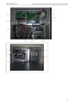
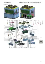
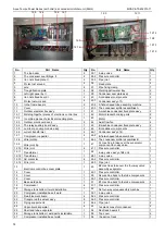
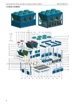
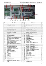
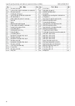
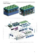
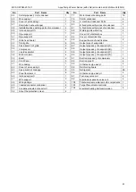
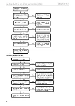
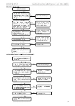
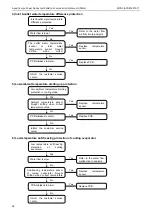
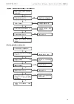
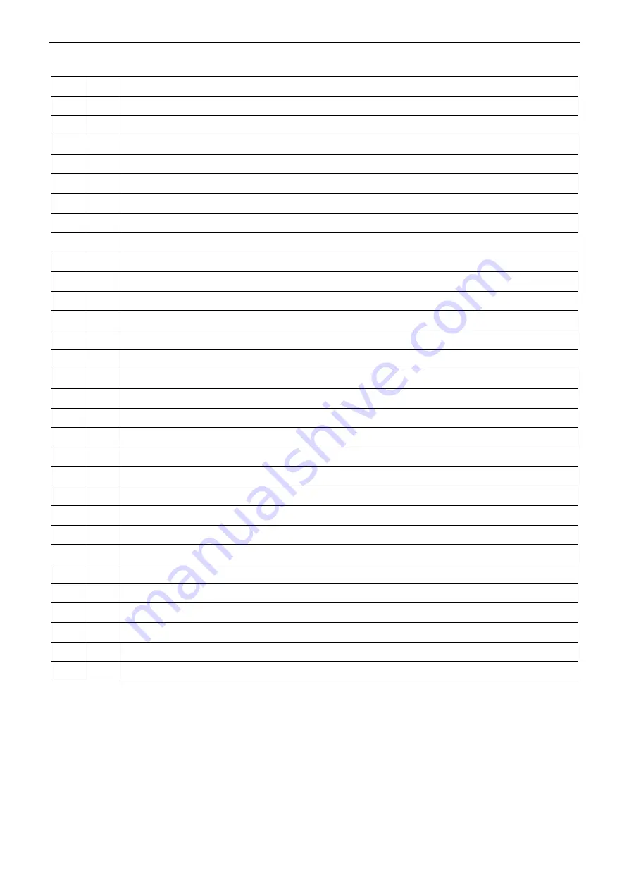
200kW module (MGBL-F200W/RN1)
No
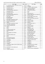
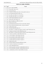
Code
Trouble
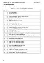
1
E0
Error of outdoor EEPROM
2
E1
Power phase sequence error
3
E2
Communication error
4
E3
Total water outlet temperature sensor error (Be valid for main unit)
5
E4
Unit outlet water temperature sensor error
6
E5
Pipe temperature sensor error in condenser A
7
E6
Pipe temperature sensor error in condenser B
8
E7
Outdoor ambient temperature sensor error
9
E8
Output of the power protector error
10
E9
Water flow detection error(Manual recovery)
11
EA
(Reserved failure code)
12
Eb
Anti-freezing
temperature sensor error in shell and tube exchanger
13
EC
Wired controller detected that the units on-line have decreased.
14
Ed
(Reserved failure code)
15
EF
Inlet water temperature sensor error
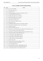
16
P0
High pressure or air discharge temperature protection in system A(Manual recovery)
17
P1
Low pressure protection in system A(Manual recovery)
18
P2
High pressure or air discharge temperature protection in system B(Manual recovery)
19
P3
Low pressure protection in system B(Manual recovery)
20
P4
Current protection in system A(Manual recovery)
21
P5
Current protection in system B(Manual recovery)
22
P6
Condenser high pressure protection in system A
23
P7
Condenser high pressure protection in system B
24
P8
(Reserved failure code)
25
P9
Outlet and inlet water temperature difference protection
26
PA
Low ambient temperature drive-up protection
27
Pb
System
anti-freezing
protection
28
Pc
Anti-freezing pressure protection in system A(Manual recovery)
29
Pd
Anti-freezing pressure protection in system B(Manual recovery)
30
PE
Low-temperature protection of evaporator(Manual recovery)
Содержание Aqua Tempo Super Series
Страница 37: ...Aqua Tempo Power Series with LAK air cooled scroll chiller unit 50Hz MCAC ATSM 2013 11 36 130kW module...
Страница 38: ...MCAC ATSM 2013 11 Aqua Tempo Power Series with LAK air cooled scroll chiller unit 50Hz 37 200kW module...
Страница 39: ...Aqua Tempo Power Series with LAK air cooled scroll chiller unit 50Hz MCAC ATSM 2013 11 38 250kW module...
Страница 45: ...Aqua Tempo Power Series with LAK air cooled scroll chiller unit 50Hz MCAC ATSM 2013 11 44 200kW module...
Страница 48: ......
Страница 62: ...MCAC ATSM 2013 11 Aqua Tempo Power Series with LAK air cooled scroll chiller unit 50Hz 61...
Страница 69: ...Aqua Tempo Power Series with LAK air cooled scroll chiller unit 50Hz MCAC ATSM 2013 11 68...
Страница 71: ...Aqua Tempo Power Series with LAK air cooled scroll chiller unit 50Hz MCAC ATSM 2013 11 70 MGBL D65W RN1...
Страница 72: ...MCAC ATSM 2013 11 Aqua Tempo Power Series with LAK air cooled scroll chiller unit 50Hz 71...
Страница 74: ...MCAC ATSM 2013 11 Aqua Tempo Power Series with LAK air cooled scroll chiller unit 50Hz 73 10 4 MGBL F130W RN1...
Страница 77: ...Aqua Tempo Power Series with LAK air cooled scroll chiller unit 50Hz MCAC ATSM 2013 11 76 10 5 MGBL F200W RN1...
Страница 80: ...MCAC ATSM 2013 11 Aqua Tempo Power Series with LAK air cooled scroll chiller unit 50Hz 79 10 6 MGBL F250W RN1...
Страница 100: ...MCAC ATSM 2013 11 Aqua Tempo Power Series with LAK air cooled scroll chiller unit 50Hz 99 55 60 65kW module 130kW module...