


35
DL451 Modular I/O
Operator Manual
Chapter 5: Getting Started
This section shows you how to connect up, switch on, set up and configure the DL451
Modular I/O unit.
Connecting up
Connect up the following, as appropriate, to the rear panel of your DL451 Modular I/O
unit:
•
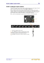
Inputs/outputs
- connect up modules in slots
A
,
B
and
C
.
These can be any
combination of modules DL441, DL442 and DL452; see page 29 in Chapter 4.
•
AES50
- connect the
AES50 audio
X and Y sockets to the appropriate
AES50
audio
sockets on the X and Y routers.
•
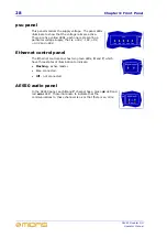
Ethernet
- connect the
Ethernet control
X and Y sockets to the appropriate
Ethernet control
sockets on the X and Y routers.
•
MIDI
- connect the three MIDI 5-pin DIN connectors, if required.
•
GPIO
- connect the 25-way D-type connectors, if required.
•
USB
- connect a laptop/PC, if required.
•
Mains power supply
- insert the IEC connector of the mains cable into the rear of
the unit and then plug it into the mains power outlet.
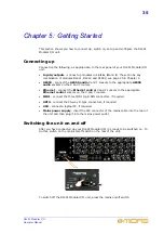
Switching the unit on and off
After you have connected up your DL451 Modular I/O it is ready to be switched on. To
do this, switch on the mains on/off switch on the rear of the unit.
To switch off the DL451 Modular I/O unit, press the mains on/off switch.
Содержание DL451
Страница 2: ......
Страница 4: ......
Страница 6: ......
Страница 16: ...xvi DL451 Modular I O Operator Manual...
Страница 20: ...4 Chapter 1 Introduction DL451 Modular I O Operator Manual...
Страница 42: ...26 Chapter 2 XL8 Live Performance System Overview DL451 Modular I O Operator Manual...
Страница 50: ...34 Chapter 4 Rear Panel DL451 Modular I O Operator Manual...
Страница 72: ...56 Appendix A Functional Block Diagram DL451 Modular I O Operator Manual...


