


28
Chapter 3: Front Panel
DL451 Modular I/O
Operator Manual
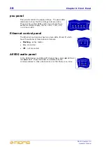
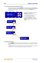
psu panel
This panel monitors the supply voltage. The panel LEDs
illuminate to show that the voltage rails are active.
There are five yellow LEDs, each one representing a
particular voltage supply, that is, +18V, -18V, +5V,
+3.3V and +48V.
Ethernet control panel
The Ethernet control panel has two green LEDs,
X
and
Y
, which
have three states of illumination to indicate:
•
Flashing
- active master.
•
On
- connected.
•
Off
- not connected.
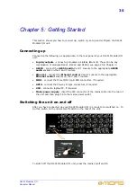
AES50 audio panel
In the AES50 panel, each
X
and
Y
channel has a green
ok
LED and
red
error
LED. These illuminate to indicate that the
communications to these channels is ok or that there is an error.
Содержание DL451
Страница 2: ......
Страница 4: ......
Страница 6: ......
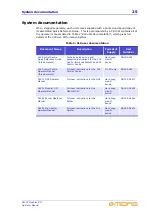
Страница 16: ...xvi DL451 Modular I O Operator Manual...
Страница 20: ...4 Chapter 1 Introduction DL451 Modular I O Operator Manual...
Страница 42: ...26 Chapter 2 XL8 Live Performance System Overview DL451 Modular I O Operator Manual...
Страница 50: ...34 Chapter 4 Rear Panel DL451 Modular I O Operator Manual...
Страница 72: ...56 Appendix A Functional Block Diagram DL451 Modular I O Operator Manual...


