


20
MDS iNET 900 Series User’s Guide
MDS 05-2806A01, Rev. E.1
NOTE:
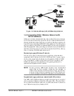
It is very important to use attenuation between all units in the
test setup. The amount of attenuation required will depend on
the number of units being tested and the desired signal strength
(RSSI) at each transceiver during the test. In no case should a
signal greater than –50 dBm be applied to any transceiver in
the test setup. An RF power output level of +20 dBm is recom-
mended. (
See “Radio Configuration Menu” on Page 48
.)
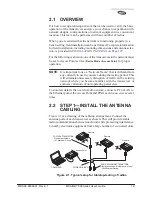
2.3
STEP 2—MEASURE & CONNECT
THE PRIMARY POWER
The primary power at the transceiver’s power connector must be within
10–30 Vdc and be capable of continuously providing a minimum of 8
Watts (typical power consumptions are: 760 mA @ 10.5 Vdc, 580 mA
@ 13.8 Vdc, and 267 mA @ 30 Vdc).
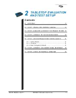
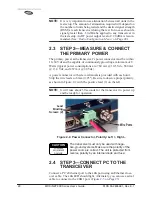
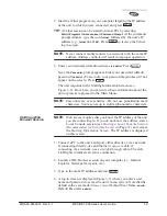
A power connector with screw-terminals is provided with each unit.
Strip the wire leads to 6 mm (0.25"). Be sure to observe proper polarity
as shown in
Figure 2-2
with the positive lead (+) on the left.
NOTE:
It will take about 30 seconds for the transceiver to power up
and be ready for operation.
Invisible place holder
Figure 2-2. Power Connector, Polarity: Left +, Right –
The transceiver must only be used with nega-
tive-ground systems. Make sure the polarity of the
power source is correct. The unit is protected from
reverse polarity by an internal diode and fuse.
2.4
STEP 3—CONNECT PC TO THE
TRANSCEIVER
Connect a PC’s Ethernet port to the
LAN
port using an Ethernet cross-
over cable. The
LAN
LED should light. Alternately, you can use a serial
cable to connect to the
COM1
port. (
Figure 2-3 on Page 23
)
Wire Ports
Lead
Screws (2)
Binding
CAUTION
POSSIBLE
EQUIPMENT
DAMAGE
Содержание iNET 900 Series
Страница 10: ...2 MDS iNET 900 Series User s Guide MDS 05 2806A01 Rev E 1 ...
Страница 26: ...18 MDS iNET 900 Series User s Guide MDS 05 2806A01 Rev E 1 ...
Страница 118: ...110 MDS iNET 900 Series User s Guide MDS 05 2806A01 Rev E 1 ...
Страница 120: ...112 MDS iNET 900 Series User s Guide MDS 05 2806A01 Rev E 1 ...
Страница 136: ...128 MDS iNET 900 Series User s Guide MDS 05 2806A01 Rev E 1 ...
Страница 148: ...140 MDS iNET 900 Series User s Guide MDS 05 2806A01 Rev E 1 ...
Страница 150: ...142 MDS iNET 900 Series User s Guide MDS 05 2806A01 Rev E 1 ...
Страница 164: ...156 MDS iNET 900 Series User s Guide MDS 05 2806A01 Rev E 1 ...
Страница 172: ...164 MDS iNET 900 Series User s Guide MDS 05 2806A01 Rev E 1 ...