


System Description 4
miriac SBC-S32V User Manual
V 1.1
31/81
© MicroSys Electronics GmbH 2017
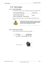
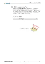
4.15.8 Power Up
During a power up sequence, the MCU first checks the input voltage to be within
their necessary limits. After that, the POL
(Point Of Load)
regulators on the module
will be activated as well as the tracking regulators for 5V, 3.3V and 1.5V on the car-
rier board. If all module voltages are o.k. the reset sequence will be started. If there
is no external reset request, f.e. via RSTIN# from the reset key, the RESET# will be
released after 100ms. A low level on the RSTIN# line extends this time. During nor-
mal operation, a falling edge at RSTIN# initiates a reset sequence for the whole
system, which is at least 100ms long. As long the reset key is pressed, the system
will be held in the reset state. If the key is released, the CPU will fetch its power up
configuration and starts up with its BIST
and/or boot sequence. The RSTOUT# sig-
nal will directly follow the
state of the RESET# signal. As long the RSTOUT# is
active all connected devices must be held in a reset state in order not to block the
power up configuration settings.
+12V
PWEN
V(intern)
RSTIN#
RSTOUT#
PORST#
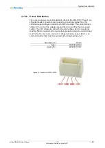
In case the MCU detects any overvoltage, it will turn off all internal point of load
regulators. The external supply voltage is reverse polarity protected and limited by
a 15V transient voltage suppressor diode to protect the system. The input poly fuse
is rated for a maximum voltage of 24V, i.e. any voltage above that limit will destroy
the input protection of the system.


