Microsens MS400863M Скачать руководство пользователя страница 6

MS400863M – User Manual


Page 

6

 of 

15


©2019_MICROSENS GmbH & Co. KG_Küferstr. 16_59067 Hamm/Germany_www.microsens.com 


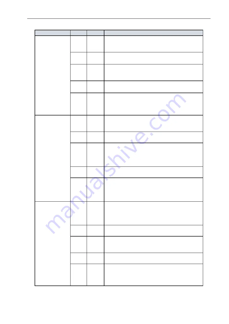
The following informs about the port LEDs: 

LED 

Color  State 

Description 

RJ-45 Ports 

Green 

On 

The port is enabled and established a link to 
connected device, and the connection speed is 
1000 Mbps. 

Green  Blinking 

The port is transmitting/receiving packets, and 
the connection speed is 1000 Mbps. 

Amber 

On 

The port is enabled and established a link to 
connected device, and the connection speed is 
10/100 Mbps. 

Amber  Blinking 

The port is transmitting/receiving packets, and 
the connection speed is 10/100 Mbps. 

-- 

Off 

The port has no active network cable connected, 
or it is not established a link to connected device. 
Otherwise, the port may have been disabled 
through the switch user interface. 

SFP Ports 

Green 

On 

The port is enabled and established a link to 
connected device, and the connection speed is 
1000 Mbps. 

Green  Blinking 

The port is transmitting/receiving packets, and 
the connection speed is 1000 Mbps. 

Amber 

On 

The port is enabled and established a link to 
connected device, and the connection speed is 
100 Mbps. 

Amber  Blinking 

The port is transmitting/receiving packets, and 
the connection speed is 100 Mbps. 

-- 

Off 

The port has no active network cable connected, 
or it is not established a link to connected device. 
Otherwise, the port may have been disabled 
through the switch user interface. 

SFP+ Ports 

Blue 

On 

The port is enabled and established a link to 
connected device, and the connection speed is  
10 Gbps. 

Blue  Blinking 

The port is transmitting/receiving packets, and 
the connection speed is 10 Gbps. 

Green 

On 

The port is enabled and established a link to 
connected device, and the connection speed is    
1 Gbps. 

Green  Blinking 

The port is transmitting/receiving packets, and 
the connection speed is 1 Gbps. 

-- 

Off 

The port has no active network cable connected, 
or it is not established a link to connected device. 
Otherwise, the port may have been disabled 
through the switch user interface. 

      Table 2: Port LEDs 


Содержание MS400863M

Страница 1: ...Gigabit Ethernet Switch With 10G Uplinks User Manual MS400863M July 2019...

Страница 2: ...RJ 45 Ports 5 3 4 SFP SFP Ports 5 3 5 LEDs 5 3 6 Management Port 7 3 7 Console Port 7 3 8 Reset Button 7 4 Installing the Switch 8 4 1 Mounting 8 4 1 1 Rack Mounting 8 4 1 2 Desktop or Shelf Mounting...

Страница 3: ...ology the entire packet must be received into a buffer and checked for validity before being forwarded This prevents errors from being propagated throughout the network Additionally the device support...

Страница 4: ...gure 1 only the earth screw is placed at the rear side 3 1 Redundant Power Interface There are dual power inputs on the front panel of the switch for power redundancy requirement the switch has 100 24...

Страница 5: ...re that the configuration of the port speed matches with the used SFP or SFP module 3 5 LEDs The switch includes a display panel for system and port indications that simplify installation and network...

Страница 6: ...1000 Mbps Green Blinking The port is transmitting receiving packets and the connection speed is 1000 Mbps Amber On The port is enabled and established a link to connected device and the connection sp...

Страница 7: ...Speed 115200 bps Data bits 8 Stop bits 1 Flow control none Parity bit none This interface can be used if the IP settings are unknown Only login default admin and password default microsens must be kno...

Страница 8: ...device Pick up the device by holding it on the left and right edges only Note The switch is an indoor device If it is to be used with outdoor devices such as outdoor IP cameras or outdoor WiFi APs th...

Страница 9: ...g the Rubber Feet 4 2 Power Supply and Grounding Before the power supply cable is connected the device must be grounded Connect the grounding screw at the rear side with protective earth of the buildi...

Страница 10: ...ep 4 Check the system LED If it is on the power connection is correct Step 5 Ensure strain relief and defined cable routing for the RJ 45 wires Figure 9 DC Power Note When wiring the DC power input it...

Страница 11: ...single mode fiber or with versa That would cause increased damping back reflections or oversteering of the receiver SFP modules are hot pluggable You can install or remove a SFP from a slot without h...

Страница 12: ...as following Step 1 Connect the switch with your PC via an Ethernet interface Step 2 Open a WEB browser and enter the IP address of the switch You can find the IP address in the CLI interface or by ch...

Страница 13: ...hipped with the device to connect the COM port of your PC with the console port Step 2 Open a terminal program and configure the RS 232 settings Step 3 Press enter Now the CLI interface appears Step 4...

Страница 14: ...s Jumbo Frames 10K Flow Control Full Duplex IEEE 802 3x Half Duplex Back pressure Twisted pair Interface Number 4 part of combo ports 1 management port Type 10 100 1000Base T Connector RJ 45 shielded...

Страница 15: ...pid Spanning Tree IEEE 802 1s Multiple Spanning Tree IEEE 802 3ad Link Aggregation Control Protocol IEEE 802 1AB Link Layer Discovery Protocol 7 Disclaimer All information in this document is provided...

Отзывы: