


Appendix
A
Connector Pinouts
A-2
Vision MINI Smart Camera Guide
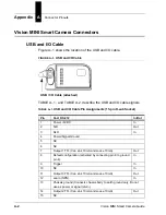
Vision MINI Smart Camera Connectors
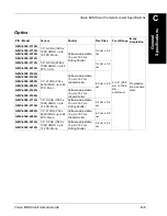
USB and I/O Cable
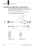
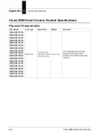
Figure A–1 shows the location of the USB and I/O cable.
FIGURE A–1.
USB and I/O Cable
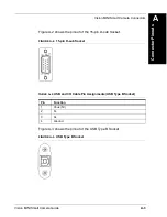
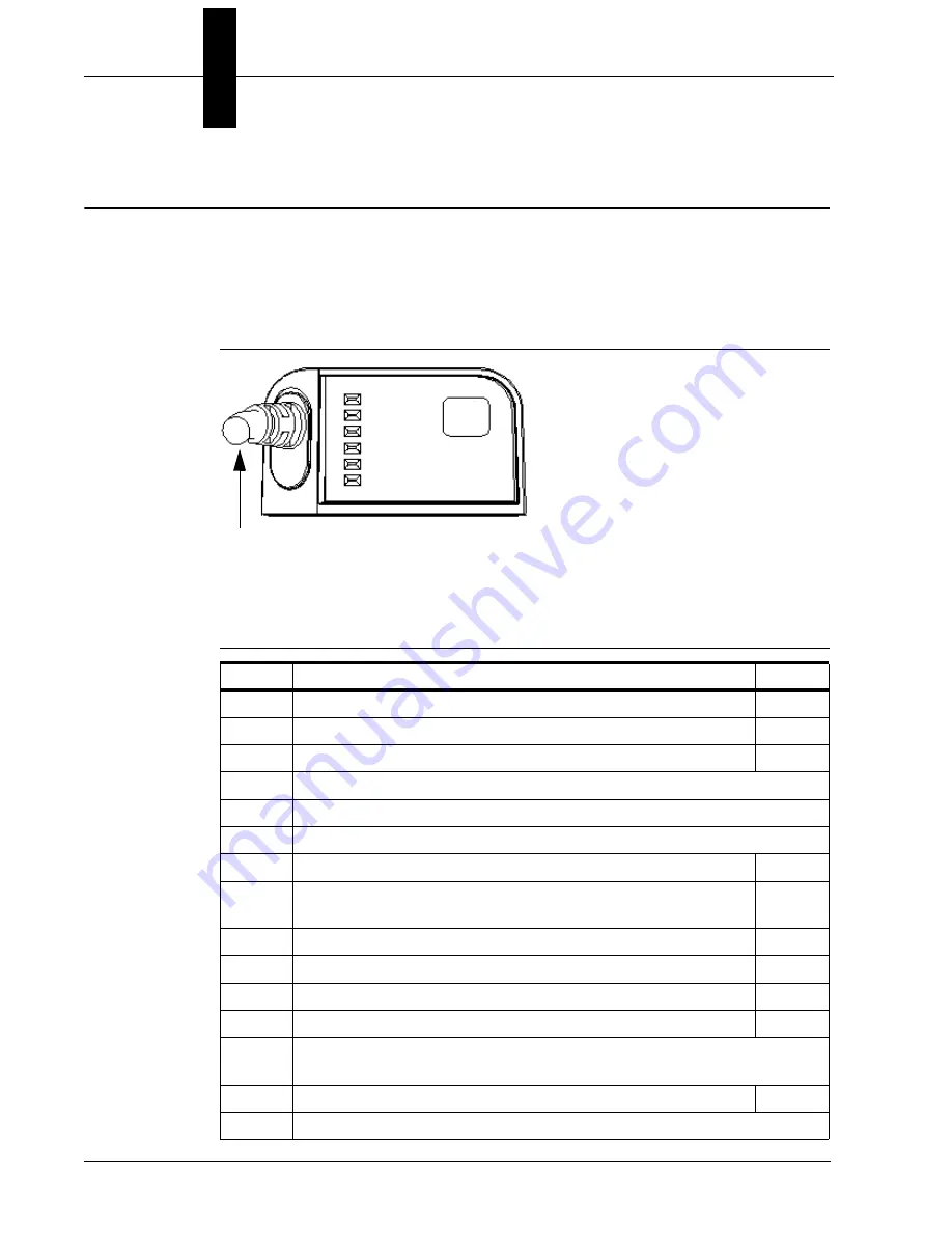
TABLE A–1. and TABLE A-2. describe the USB and I/O cable signals.
TABLE A–1.
USB and I/O Cable Pin Assignments (15-pin D-sub Socket)
Pin
Host RS-232
In/Out
1
Power +5VDC
In
2
TxD
Out
3
RxD
In
4
Power/Signal Ground
5
NC
6
NC
7
Output 1 TTL (Can sink 10mA and souce 10mA)
Out
8
Default configuration (activated by connecting pin 8 to ground
pin 4)
In
9
Trigger
In
10
NC
In
11
Output 3 TTL (Can sink 10mA and souce 10mA)
Out
12
Learn (NPN)
In
13
Chassis ground (Connects chassis body to earth ground only. Do not
use as power or signal return.)
14
Output 2 TTL (Can sink 10mA and souce 10mA)
Out
15
NC
USB / I/O Cable (attached)
Содержание Vision MINI Smart Camera
Страница 1: ...Vision MINI Smart Camera Guide 84 016300 02 Rev J ...
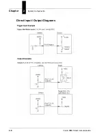
Страница 16: ...Chapter 2 System Components 2 6 Vision MINI Smart Camera Guide Direct Input Output Diagrams ...
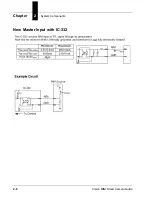
Страница 18: ...Chapter 2 System Components 2 8 Vision MINI Smart Camera Guide New Master Input with IC 332 ...
Страница 24: ...Chapter 2 System Components 2 14 Vision MINI Smart Camera Guide ...
Страница 32: ...Appendix A Connector Pinouts A 4 Vision MINI Smart Camera Guide ...
Страница 42: ...Appendix B Cable Specifications B 10 Vision MINI Smart Camera Guide ...
Страница 62: ...Appendix E Vision MINI Diagnostic Boot Mode E 4 Vision MINI Smart Camera Guide ...
Страница 66: ...Appendix F USB Power Management F 4 Vision MINI Smart Camera Guide ...


