
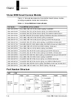


Mounting and Wiring the Vision MINI Smart Camera
System Component
s
2
Vision MINI Smart Camera Guide
2-5
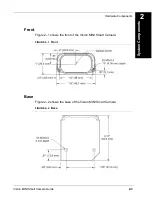
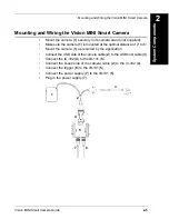
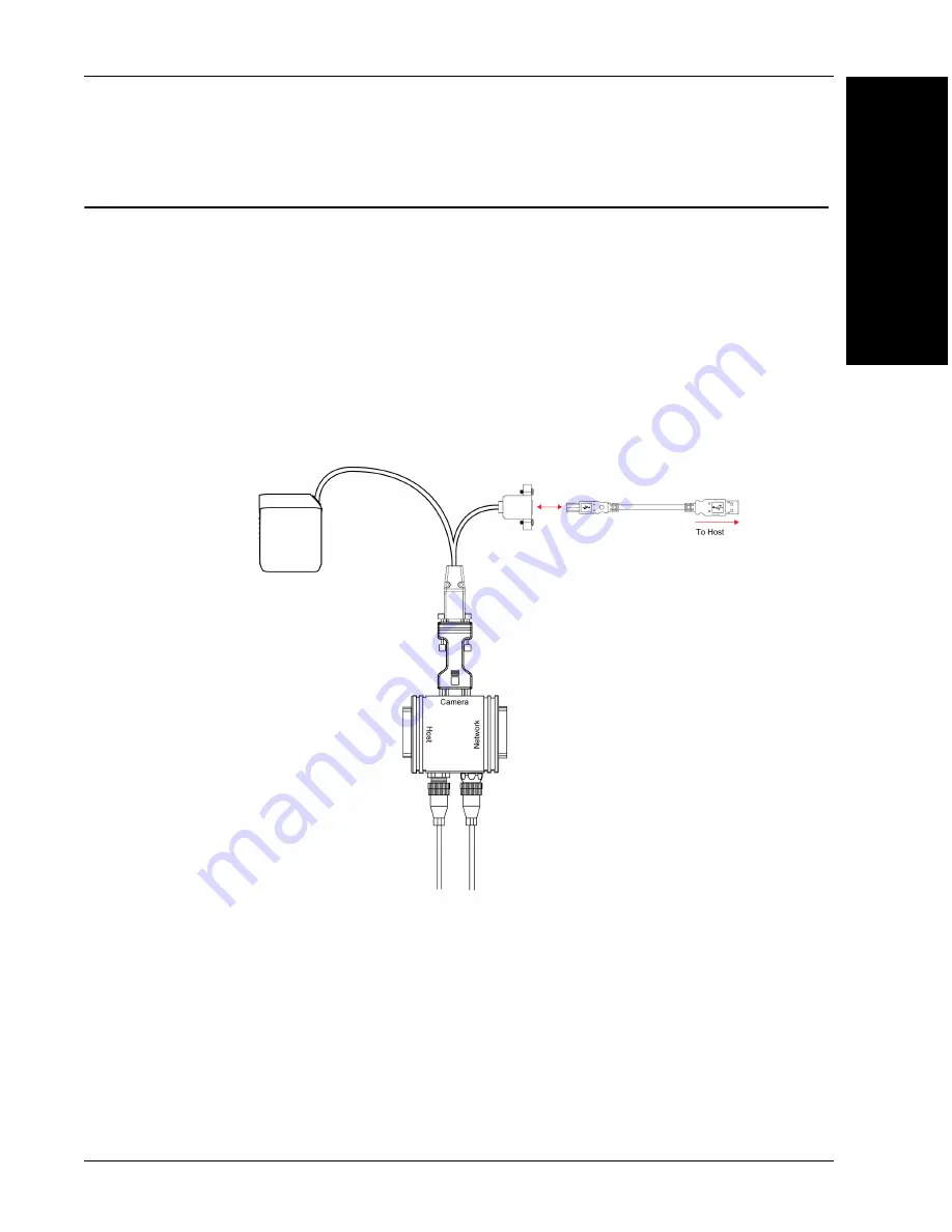
Mounting and Wiring the Vision MINI Smart Camera
•
Mount the camera (
1
) securely in its camera stand (not supplied).
•
Make sure the camera (
1
) is mounted at the optimal distance of 2” to 6”.
•
Mount the camera (
1
) as required by the application.
•
Connect the USB side of the camera cable (
2
) to the USB host cable (
3
).
•
Connect the IC-332 (
4
) to the IB-131 (
5
).
•
Connect the D-sub side of the camera cable (
2
) to the IC-332 (
4
).
•
Connect the trigger (
6
) to the IB-131 (
5
).
•
Connect the power supply (
7
) to the IB-131 (
5
).
•
Plug in the power supply (
7
).
7
1
2
3
6
4
5
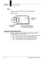
Содержание Vision MINI Smart Camera
Страница 1: ...Vision MINI Smart Camera Guide 84 016300 02 Rev J ...
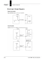
Страница 16: ...Chapter 2 System Components 2 6 Vision MINI Smart Camera Guide Direct Input Output Diagrams ...
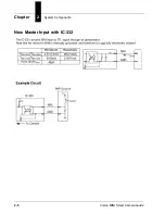
Страница 18: ...Chapter 2 System Components 2 8 Vision MINI Smart Camera Guide New Master Input with IC 332 ...
Страница 24: ...Chapter 2 System Components 2 14 Vision MINI Smart Camera Guide ...
Страница 32: ...Appendix A Connector Pinouts A 4 Vision MINI Smart Camera Guide ...
Страница 42: ...Appendix B Cable Specifications B 10 Vision MINI Smart Camera Guide ...
Страница 62: ...Appendix E Vision MINI Diagnostic Boot Mode E 4 Vision MINI Smart Camera Guide ...
Страница 66: ...Appendix F USB Power Management F 4 Vision MINI Smart Camera Guide ...