


Chapter
2
System Components
2-12
Vision MINI Smart Camera Guide
Trigger Debounce
Trigger Debounce
is the ability of the system to accomodate switching noise on a trigger state
change – a common issue with relays that have some intermittent contact while engaging.
Trigger overruns (when the vision system is triggered faster than the device can process)
can be avoided by increasing the “debounce” time in the camera definition file located in
the C:\Microscan\Vscape\Drivers\CamDefs directory.
The IO Line Debounce High Time and IO Line Debounce Low Time can be added to the
file as in the example below. The default debounce time is 1 ms (1,000
μ
s).
Note:
Although the value entered for the "IO Line Debounce Time" is in microseconds, it
will only be rounded up to a millisecond value. For example, entering the value
1001
will
resolve to 2 ms; entering a value of
2800
will resolve to 3 ms.
The min value for "IO Line Debounce Time" is 0, which disables software debounce
altogether. The maximum value is 100000 (100 ms).
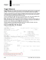
Camera Definition File Example
// Camera Definition File
// Version: 1.02
Camera Name
VisionMINI 1280x1024 // Name Displayed in
Camdef Selection Dialog
Digitizer Type
5000
// Number
associated with VisionMini SXGA
Stride
1280
// Image Width
Rows
1024
// Image Height
X Offset
0
// Image X Offset
Y Offset
0
// Image Y Offset
Bits Per Pixel
8
// Bits that represent Pixel Value
Pixel Type
0
// Type of Pixel:
MONOCHROME=0, COLOR_RGB=1, COLOR_BGR=2, COLOR_BAYGR8=3, COLOR_BAYRG8=4,
COLOR_BAYGB8=5, COLOR_BAYBG8=6, COLOR_HSI=7
Image Structure
1
// Pixel Organization: Packed=1, TwoPlanes =
2, ThreePlanes = 3
Async Control
1
// Controllable shutter time. Usually
using a pulse width specified in usecs
Usecs Per Frame
62500
// Fastest time to acquire a frame: 16 FPS
// -1 Disables timeout feature
X Offset
0
Y Offset
0
// IO Configuration
GPIO Edit Mask
0x0000
GPIO Defaults
0x0001 // 1 General Purpose Input 3 General Purpose
Outputs
GPIO Count
4
GPIO Inputs
1
GPIO Outputs
3
Sensors
1
// One input dedicated
to Trigger signal
Strobes
0
Virtual IO
2048
IO Line Debounce High Time 2000 //usecs
IO Line Debounce Low Time 2000 //usecs
// Focus & Photometry Ranges
Содержание Vision MINI Smart Camera
Страница 1: ...Vision MINI Smart Camera Guide 84 016300 02 Rev J ...
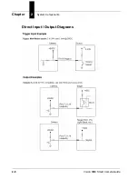
Страница 16: ...Chapter 2 System Components 2 6 Vision MINI Smart Camera Guide Direct Input Output Diagrams ...
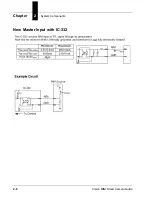
Страница 18: ...Chapter 2 System Components 2 8 Vision MINI Smart Camera Guide New Master Input with IC 332 ...
Страница 24: ...Chapter 2 System Components 2 14 Vision MINI Smart Camera Guide ...
Страница 32: ...Appendix A Connector Pinouts A 4 Vision MINI Smart Camera Guide ...
Страница 42: ...Appendix B Cable Specifications B 10 Vision MINI Smart Camera Guide ...
Страница 62: ...Appendix E Vision MINI Diagnostic Boot Mode E 4 Vision MINI Smart Camera Guide ...
Страница 66: ...Appendix F USB Power Management F 4 Vision MINI Smart Camera Guide ...


