Optical Strain Gages |
os3150 os3155
C o p y r i g h t © 2 0 1 3 M i c r o n O p t i c s , I n c .
o s 3 1 5 0 o s 3 1 5 5 I n s t a l l a t i o n G u i d e , R e v i s i o n C
2
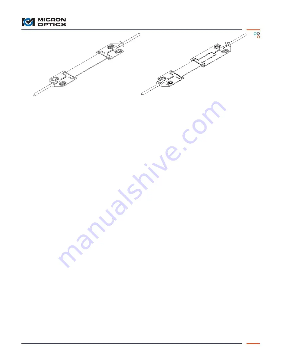
Figure 1
–
os3150 Gage
Figure 2
–
os3155 Gage
Introduction:
This installation guide details the installation of both the os3150 and os3155 strain gages shown in Figures 1 and 2.
These gages are similar in construction except that the os3155 includes a second FBG for temperature
compensation. Also the os3150 has a 75mm gage length where the os3155 has a 50mm gage length.
These gages are designed to be spot welded to a steel specimen. A portable capacitive-discharge spot welder having
50 watt-seconds minimum energy rating is recommended for best results. The spot welder should be equipped with a
small welding electrode having a spherical tip measuring approximately .030 inches [.76 mm] in diameter. It is often
helpful to practice weld technique using a blank gage. Best results are usually obtained with a setting of 50 to 200
watt-seconds and firm pressure on the electrode. After making a practice weld, pull the gage off of the surface. A
properly formed weld will result in a small piece of the surface or gage to break away. If needed, adjust the weld
energy and electrode pressure until a satisfactory weld is obtained. (Contact Micron Optics for Welder
recommendation)
Accurate strain measurement requires that the surface temperature of the specimen be measured as close to the
strain gage as possible. The os3155 facilitates this by incorporating a built-in temperature compensation FBG. In
addition, accurate measurement requires that the Stain gage, temperature compensator, and test specimen surface
be at or near the same temperature. A layer of insulation over the sensor will help to reduce the temperature
variations between these elements. A light colored or reflective surface will also help in situations where the gage will
be exposed to direct sunlight.
For reliable operation it is essential that the installed gage be protected from physical damage, moisture, and
corrosion. Various methods may be used to protect the installed gage depending on the application. This document
outlines a typical protection method utilizing a waterproof seal and stainless steel cover.
Surface preparation:
The surface must be properly prepared by removing all paint, rust, scale, oil, and grease. In order to achieve good
adhesion of the waterproof seal and protective paint it is necessary to prepare the surface according to (SSPC-SP10
/ NACE 2 Near-White Blast Cleaning) standards. The (SSPC-SP10 / NACE 2) surface finish is to coarse for the area
where the sensor will be welded. It is necessary to abrade the weld area with 60 grit silicon carbide paper.
Clean surface with a compatible solvent to remove all oil and grease. Non-Chlorinated Brake works well and
is readily available.
Prepare a rectangular area 6 x 10 inches [150 x 250mm] to (SSPC-SP10 / NACE 2). Micron Optics
recommends the use of a MONTI Bristle Blaster® for preparing surfaces in the field.
MONTI
- Werkzeuge GmbH
Reisertstr. 21
53773 Hennef Germany
http://www.bristle-blaster.com
Abrade the area immediately under where the sensor will mount 1.5 x 6 inches [38 x 150mm] with 60 grit or
finer silicon carbide paper to further smooth the surface. Do not abrade the surface around the perimeter of


