MicroLux Laserkinfe 2525 Скачать руководство пользователя страница 9

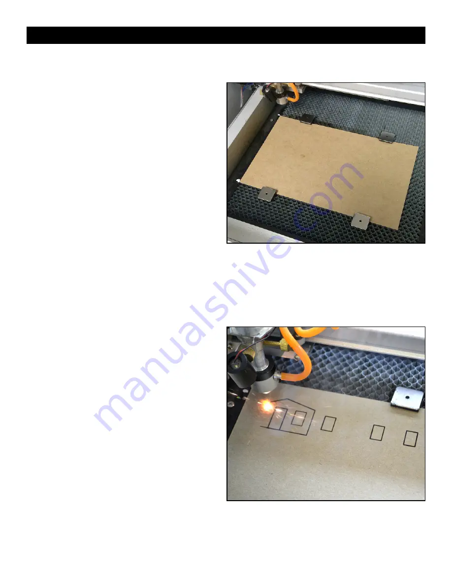
For the initial test, let’s load a piece of the provided 6” x 9” chipboard onto the honeycomb platform as shown below; that is,
all the way to the left edge, and centered in the lens’ range of motion from front-to-back.

Tip:  We  put  a  couple  of  dots  of  white  paint  on  our
platform frame to help reload subsequent chipboards in
the  same  location.  This  will  avoid  having  to  reset  the
starting  crosshair  position.  You  may  prefer  to  use  a
couple of the supplied magnets along the bottom edge
of the piece as a location guide.

Use  the  provided  magnets  to  hold  the  chipboard  tight  to
the platform so that the laser stays focused.

Notice  the  tiny  red  dot  projected  onto  the  chipboard.  This
is  not  the  laser  beam.  This  is  an  LED  marker  that  shows
where  the  laser  beam  is  aimed.  The  laser  beam  will
ultimately be seen as a bright white flash of light.

Close  the  lid.  Turn  the  dial  to  the  half-way  position  and
depress  the  “cutting”  switch  to  its  down  position  (this
allows the laser to fire). Now, quickly press and release the
“Test” button. Notice the burst of white light that the laser
fires  at  the  chipboard.  The  little  burned-through  spot
should align with the projected red dot. If not, turn off the cutting switch and current dial, then reach into the chamber to
adjust  the  projector/LED  housing  so  they  are  aligned  when  you  again  perform  a  test  fire.  In  this  way,  you’ll  be  able  to
pinpoint the starting point of the laser.

Going back to the computer screen…

In the upper left corner of the object image, two dotted cross-hairs will be visible.

Tip:  Depending  on  the  type  of  monitor  and  its  resolution  settings,  small  objects  may  appear  as  white  outlines,
which you can see if you move your head to the side a bit.

You  can  click  and  drag  the  image  to  locate  the  cutting
head  (the  lens)  in  a  good  starting  spot  on  the  chipboard
(you should see the carriage move inside the machine) so
that the entire image can be cut out without running off the
board or across the magnets. If you think you’re in a good
location, click on “Starting” (under the Properties button . . .
if  you  forgot  to  install  the  USB  “key,”  you’ll  be  reminded
right  here)  and  let  the  machine  go  through  the  cutting
routine (while the laser is still off). Watch the red pointer to
verify the correct travel. If the start position is okay, then at
the end of this “dry run,” depress the “cutting” button to its
down position, and turn up the dial to about 1/3 full current.
Then, click on “starting” again and the machine should cut
out the parts.

If  all  went  well,  and  you  have  the  sound  turned  on,  the
computer will play a “TA-DA” when the cutting operation is
finished. Congratulations!

Remove  the  parts  and  the  sheet.  We  suggest  using  a
vacuum cleaner to clean out stray cuttings from the cabinet.

Let’s Try Cutting Out Some Parts (continued)

9

Содержание Laserkinfe 2525

Страница 1: ...wners manual What s included on the Micro Mark web site 1 CorelLASER software 1 Set of sample part drawings What you ll need to provide 1 Computer running Windows 2000 or later 1 CorelDRAW software ve...

Страница 2: ...ood and plastic It will easily cut and or burn human flesh and will cause injury if you are not careful to avoid contact with the laser beam Do NOT reach into the cabinet unless the machine is switche...

Страница 3: ...r OFF whenever the main power cord has power no matter whether the position of the Master switch is set to ON or OFF Ancillary equipment provided with the machine includes A small air pump to blow deb...

Страница 4: ...nto the socket on the rear of the cabinet labeled Fan or Exhaust Note this equipment operates on 220vAC do not plug into 110vAC wall outlet Tip if the equipment plugs enter the sockets a bit too loose...

Страница 5: ...to the pump for leakage IMPORTANT You may also have to gently lift the pump out of the water and set it back in to prime the pump for proper water flow which is critical to the life of the laser tube...

Страница 6: ...ws 2000 and later operating systems Please note CorelLASER software is not compatible with Home Student versions of CorelDRAW CorelDRAW must be loaded onto the computer before CorelLASER can be downlo...

Страница 7: ...to activate the new device ID and initialize installation of the software OK now it s time to open a drawing file and cut out some parts We ve included a couple of simple sample files to get you star...

Страница 8: ...t of bounds match the settings and in no case should either dimension exceed 250 mm 9 84 inches Tip The Common Parameter Release button allows the lens to be pushed by hand out of the way Make sure po...

Страница 9: ...o they are aligned when you again perform a test fire In this way you ll be able to pinpoint the starting point of the laser Going back to the computer screen In the upper left corner of the object im...

Страница 10: ...press Delete on your keyboard Select the rear wall and cut again in a blank spot on the material The window opening is no longer cut into the wall For another example try dragging the window to a diff...

Страница 11: ...ning magnets around the edges of the material and in the center as well obviously avoiding the cut lines will help hold the material from shifting after being cut Adding frets to the drawing will keep...

Страница 12: ...se restrained by the system drive belts motors If you will be cutting multiple pieces of material in the same pattern devise a little fixture to position new pieces of material when loading the cuttin...

Страница 13: ...B port Also check that the USB cable is still connected properly and the machine is powered up If the laser tube is replaced or the machine experiences strong shock and no longer cuts properly is ther...

Страница 14: ...I cut materials of different thickness the cutting or engraving isn t as sharp as it should be Can I compensate for this The lens can be shifted up or down to accommodate workpieces of different thic...

Страница 15: ...or outline and adjust each mirror in sequence using the jack screws and lock nuts so that the burn mark is centered in the outline This will assure full laser output is reaching the lens and subsequen...

Страница 16: ...T H E S M A L L T O O L S P E C I A L I S T S 340 Snyder Avenue Berkeley Heights NJ 07922 www micromark com Tech Support 908 464 1094 weekdays 1pm to 5pm ET MMTechService micromark com...

Страница 17: ...d download the files to your computer under the default settings which should put the zip files into your Documents Downloads folder of your computer Double left click CorelLASERMasterFiles zip Double...

Отзывы: