micro
HAM ©
2016
All rights reserved
Switching
The Switching tab contains two
columns for InVectors because Stack
Switch has two R ports, MAIN and
SUB. All Output combinations are
related to both InVectors applied at
once according to Stack Switch internal
control logic.
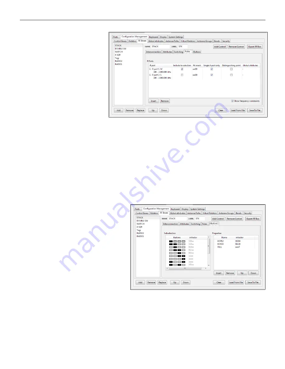
Rules
R port
column again defines
frequency ranges for both R ports.
Include to selection
is active when
Stack Switch is enabled (selected). It is important because Stack control is different than normal switch control.
Antennas connected to the Stack Switch should have at least one band in common. When the R port is added
to the selection, the combination of stacked antennas can be controlled by sub selection buttons.
Fit mask
is set to xxx00. It means that all Stack Switch antenna combinations will be added to the further
processing. Router handles disconnected A ports automatically. It is not necessary to change fit mask if some A
port of the Stack Switch (or any other RF box A ports) is not connected, for example, if only two antennas are
stacked.
When
Single A port only
is enabled no stack combination will be offered as a main selection – only single A
port selections (ANT1 or ANT2 or ANT3 alone) will be offered. In this case, Stack Switch will act much like a
“Double Three” switch. If direct selection of a specific stack combination is desired (for example ANT2+ANT3),
the
Single A port only
checkbox must be disabled.
Distinguishing point
and
Global attributes
are advanced parameters and will be explained separately.
Buttons
All RF boxes which have more than one InVector
(more than one control) can also have an
association between the InVectors and
Subselection
buttons. These associations are
defined at Buttons tab and shows which InVector
will be selected for each of the fifteen (15) valid
combinations of the subselection buttons.
The InVector can have explicit form like 10000, it
can contain an
X
- meaning
“don't change last
state”
for this bit, or it can contain a
T
– meaning
“invert (toggle) the last state”
of this bit.
The
Properties
field provides another way to
apply an InVector. In addition to applying (selecting) the InVector using the main antenna selection buttons
(buttons 1 .. 7 on front panel) or the Subselection buttons, the InVector can be chosen using the the
PATH
properties button. When this button is pressed, the bottom line of SMD display shows all of the choices defined
in Properties list. Each property can then be applied by one of seven main selection buttons. Because the name
is not shown on the SMD display, PATH properties should be reserved for selecting special features of the RF
box. In case of Stack Switch, PATH properties are useful for selecting BOP features (out of phase states) or the
FULL property (takes exclusive control of Stack Switch and prevent any other radio [SMD] from using an un-
used antenna through the SUB port).
63
Содержание STATION MASTER DeLuxe
Страница 119: ...microHAM 2016 All rights reserved 119...
Страница 123: ...microHAM 2016 All rights reserved 123...


