BIGHORN_March 2020.docx
March 26, 2020
Page
23 of 36
Flexible Lines
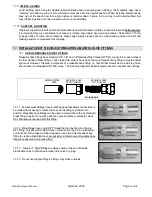
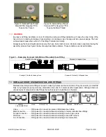
Flexible nozzle lines will require a nozzle orientation tool, MicroCool Part # TKT0001 as shown in Figure 10.
The nozzle orientation tool is clamped onto the crimp ferrules on each side of the nozzle and held firmly with one
hand. A piece of 3/8" tube is then slid over the end of the nozzle. This is then used with moderate force to rotate the
nozzle into the desired position. See diagram A. Make sure that the tool is tightly clamped and that the hose does
not move on either side of the tool as the nozzle is turning.
If the nozzle will not turn using the 3/8” tube and moderate force, do not increase the amount of force. Instead a
small pair of vise grips can be used to grasp the nozzle barb body (not the nozzle) and rotate it into the desired
position. See diagram B.
It is not recommended that a wrench or vise pliers be used to grab the nozzle and twist into
position, as the nozzle stem is likely to be broken.
17.1
NOZZLE ANGLE
Nozzle angle can vary depending on application. Contact a MicroCool Specialist for recommendations on best
angles for different applications.
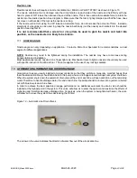
NOTE:
Nozzles may need to be tightened during the installation. The nozzles may have come loose during
transportation and installation.
Most applications require nozzles to be finger tight only. Mechanical tools to tighten nozzles should only be used
with specific instruction from MicroCool. The same applies to the use of any locking sealants.
18.
ATOMIZATION LINE/MANIFOLD HOSE DRAINAGE
Atomization lines are usually installed at proper gradients so that they self-drain. Generally, manifold hoses (that
feed the atomization lines) should drain back to the pump where a drainage solenoid will open at system shutdown.
When the system shuts down the automatic drain valve at the end of each line will open and drain out the remaining
water. Therefore to handle drainage water, the end of each line if possible should be routed into a gutter or directed
out with blue low-pressure blue hose.
In order to achieve the best possible drainage performance, an additional automatic line drain valve should be
installed at the highest point in the system. This valve will allow air to enter the system and maximize the effects of
siphoning and therefore decrease drainage time. Conversely, when the system is being filled with water, the valve
will allow air to leave the system thus decreasing the fill time.
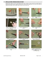
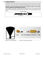
Figure 12 – Automatic Line Drain Valves
The arrow on the valve indicates the direction of water flow out of the atomization line.
Содержание BIGHORN 1000
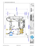
Страница 28: ...BIGHORN_March 2020 docx March 26 2020 Page 28 of 36 22 BIGHORN ILLUSTRATIONS...
Страница 29: ...BIGHORN_March 2020 docx March 26 2020 Page 29 of 36 22 1 BIGHORN FRONT EXTERNAL VIEW...
Страница 30: ...BIGHORN_March 2020 docx March 26 2020 Page 30 of 36 22 2 BIGHORN BACK EXTERNAL VIEW...
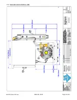
Страница 31: ...BIGHORN_March 2020 docx March 26 2020 Page 31 of 36 22 3 BIGHORN RIGHT EXTERNAL VIEW...
Страница 32: ...BIGHORN_March 2020 docx March 26 2020 Page 32 of 36 22 4 BIGHORN LEFT EXTERNAL VIEW...
Страница 33: ...BIGHORN_March 2020 docx March 26 2020 Page 33 of 36 22 5 BIGHORN TOP EXTERNAL VIEW...
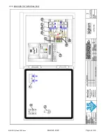
Страница 34: ...BIGHORN_March 2020 docx March 26 2020 Page 34 of 36 22 6 BIGHORN TOP INTERNAL VIEW...
Страница 35: ...BIGHORN_March 2020 docx March 26 2020 Page 35 of 36 22 7 BIGHORN CONTROL PANEL VIEW...
Страница 36: ...BIGHORN_March 2020 docx March 26 2020 Page 36 of 36 22 8 NOTES...


