background image

3.5.10 

On-Board Debugger Implementation

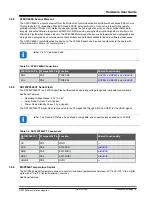
AVR-BLE features an on-board debugger that can be used to program and debug the ATmega3208 using UPDI. The
on-board debugger also includes a virtual serial port (CDC) interface over UART and debug GPIO. Atmel Studio/
Microchip MPLAB

®

 X IDE can be used as a front-end for the on-board debugger for programming and debugging. 

MPLAB Data Visualizer

 can be used as a front-end for the CDC and debug GPIO.

3.5.10.1  On-Board Debugger Connections

The table below shows the connections between the target and the debugger section. All connections between the
target and the debugger are tri-stated as long as the debugger is not actively using the interface. Hence, since there
are little contaminations of the signals, the pins can be configured to anything the user wants.

For further information on how to use the capabilities of the on-board debugger, see 

3.1  On-Board Debugger

Overview

.

Table 3-11. On-Board Debugger Connections

ATmega3208 Pin Debugger Pin

Function

Shared Functionality

PF1

CDC TX

UART2 RX (ATmega3208 RX line)

PF0

CDC RX

UART2 TX (ATmega3208 TX line)

UPDI

DBG0

UPDI

PF4

DBG1

DEBUG GPIO1

Data LED

PF3

DBG2

DEBUG GPIO0

SW0

 and 

RN4870


Hardware User Guide

©

 2020 Microchip Technology Inc.

 User Guide

DS50002956A-page 21

Содержание AVR-BLE

Страница 1: ...A secure element Connected represented by the RN4870 BLE module In addition the AVR BLE Development Board features the following elements The on board debugger PKoB nano supplies full programming and debugging support through Atmel Studio Microchip MPLAB X IDE It also provides access to a serial port interface serial to USB bridge and two logic analyzer channels debug GPIO A mikroBUS socket enable...

Страница 2: ... Peripherals 15 4 Hardware Revision History and Known Issues 22 4 1 Identifying Product ID and Revision 22 4 2 Revision 3 22 4 3 Revision 2 22 5 Document Revision History 23 6 Appendix 24 6 1 Schematics 24 6 2 Assembly Drawing 27 The Microchip Website 28 Product Change Notification Service 28 Customer Support 28 Microchip Devices Code Protection Feature 28 Legal Notice 28 Trademarks 29 Quality Man...

Страница 3: ...erial port USB CDC Two logic analyzer channels DGI GPIO USB or Battery Powered 1 2 Board Overview The AVR BLE development board is a hardware platform that is being used to evaluate the ATmega3208 AVR microcontroller and RN4870 BLE module Figure 1 1 AVR BLE Development Board Front Side Micro USB Connector Debugger Power Status LED ATECC6080A Crypto Data LED Green Error LED Red SST25PF040CT Serial ...

Страница 4: ...Figure 1 2 AVR BLE Development Board Back Side CR2032 Battery Holder Additional RN4870 GPIO Introduction 2020 Microchip Technology Inc User Guide DS50002956A page 4 ...

Страница 5: ...T PF2 SPI MOSI PA4 BMA 253 INT2 PC3 MIC33050 DC DC Converter BMA253 Acceleration Sensor ATECC608A Secure Element PD1 PD6 PC1 PC0 PA3 PA2 5 0V GND SST25PF040C 4MB FLASH PF4 PF5 Micro USB Connector PKoB Nano Debugger Programmer MCP9844 Temperature Sensor AN RST SPI CS SPI SCK SPI MISO SPI MOSI 3 3V GND ATmega3208 MCU User Switch 0 RN4870 Bluetooth Low Energy Module PD7 PD5 PA7 PA6 PA5 PA4 PF3 PWM IN...

Страница 6: ...to create a custom application 1 View the source code at the avr lightblue explorer demo GitHub page 2 Read through the README md to get more information on how to expand the solution 3 Download the project from GitHub and open it in the latest version of MPLAB X IDE 4 Connect a USB cable Standard A to Micro B or Micro AB between the Windows Mac or Linux device and the debug USB port on the AVR BL...

Страница 7: ...erface to configure peripherals and functions specific to your application Atmel START Atmel START is an online tool that helps the user to select and configure software components and tailor your embedded application in a usable and optimized manner Microchip Sample Store Microchip sample store where you can order samples of devices MPLAB Data Visualizer MPLAB Data Visualizer is a program used fo...

Страница 8: ...ly during power up Power up The LED is ON Normal operation The LED is ON Programming Activity indicator The LED blinks slowly during programming debugging Drag and drop programming Success The LED blinks slowly for 2 sec Failure The LED blinks rapidly for 2 sec Fault The LED blinks rapidly if a power Fault is detected Sleep Off The LED is OFF The on board debugger is either in a sleep mode or powe...

Страница 9: ...s the CDC will enumerate as Curiosity Virtual COM Port and appear in the Ports section of the Windows Device Manager The COM port number can also be found there Info On older Windows systems a USB driver is required for CDC This driver is included in installations of Atmel Studio Microchip MPLAB X IDE On Linux machines the CDC will enumerate and appear as dev ttyACM Info tty devices belong to the ...

Страница 10: ...connected to the debugger s CDC TX pin 3 1 2 5 Advanced Use CDC Override Mode In normal operation the on board debugger is a true UART bridge between the host and the device However in certain use cases the on board debugger can override the basic operating mode and use the CDC TX and RX pins for other purposes Dropping a text file into the on board debugger s mass storage drive can be used to sen...

Страница 11: ...EX file the binary data are encoded in ASCII with metadata providing a large overhead so one MB is a trivially chosen value for disk size It is not possible to format the CURIOSITY drive When programming a file to the target the filename may appear in the disk directory listing This is merely the operating system s view of the directory which in reality has not been updated It is not possible to r...

Страница 12: ...ry according to the programming interface of the target device Debugger firmware v1 16 or newer Info The commands listed here are triggered by the content being sent to the mass storage emulated disk and no feedback is provided in the case of either success or failure 3 1 4 Data Gateway Interface DGI Data Gateway Interface DGI is a USB interface for transporting raw and time stamped data between o...

Страница 13: ...ements at 2 MHz frequency providing a timestamp resolution of a half microsecond 3 2 Power Supply The board can be powered through the USB port or by a CR2032 battery It will automatically switch to the battery if USB power is not available While powered through USB the board generates 3 3V for the debugger ATmega3208 and peripherals During battery operation the ATmega3208 and peripherals run dire...

Страница 14: ...8 I O pins as input and disable the digital input buffer Important USART pins PF0 and PF1 are connected directly to the on board debugger It is important to tri state the USART pins when the board is powered from a CR2032 battery to prevent powering the debugger through its I O pins Doing so will increase the power consumption and cause undefined behavior from the on board debugger Info The load s...

Страница 15: ...r is not needed anymore place a jumper cap on the pin header 3 5 Peripherals 3 5 1 ATmega3208 Microchip ATmega3208 is a microcontroller featuring the AVR processor with hardware multiplier running at up to 20 MHz and with 32 KB Flash 4 KB SRAM and 256 bytes of electrically erasable programmable read only memory EEPROM in a 28 or 32 pin package It uses the latest Core Independent Peripherals CIPs w...

Страница 16: ...2 54 mm pitch female headers and is ready to mount add on boards Table 3 3 mikroBUS Socket Pinout mikroBUS Socket Pin ATmega3208 Pin Function Shared Functionality AN PD7 ADC AIN7 RST PD5 GPIO CS PA7 SPI0 CS SCK PA6 SPI0 SCK SST25PF040CT MISO PA5 SPI0 MISO SST25PF040CT MOSI PA4 SPI0 MOSI SST25PF040CT 3 3V VDD VCC_TARGET GND GND Ground PWM PD1 TCA0 WO1 INT PD6 GPIO RX PC1 UART1 RX TX PC0 UART1 TX SC...

Страница 17: ...om the ATmega3208 the debugger as well as by a physical switch allows the module to be put in a Test Mode where the RN4870 firmware can be updated The module has one of its GPIO pins connected to an LED By default this will indicate connection status but the user can configure it for a number of other functions Many of the other RN4870 GPIO pins are available as pads around the label on the back s...

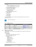
Страница 18: ...ns ATECC608A Pin ATmega3208 Pin Function Shared Functionality SDA PA2 TWI0 SDA MCP9844 BMA253 and mikroBUS SCL PA3 TWI0 SCL MCP9844 BMA253 and mikroBUS 3 5 5 SST25PF040CT Serial Flash The SST25PF040CT is a 4 Mbit Serial Flash with extended operating voltage range and low power consumption Additional Features Operating Voltage Range 2 3V to 3 6V Active Read Current 5 mA typical Power Down Standby C...

Страница 19: ...x18 Table 3 7 MCP9844 Connections MCP9844 Pin ATmega3208 Pin Function Shared Functionality SDA PA2 TWI0 SDA ATECC608A BMA253 and mikroBUS SCL PA3 TWI0 SCL ATECC608A BMA253 and mikroBUS Event PF2 ASYNC External Interrupt 3 5 7 BMA253 Acceleration Sensor The Bosch BMA253 is a low g acceleration sensor with digital output for measurements of acceleration in three perpendicular axes Additional Feature...

Страница 20: ...ng their connected I O lines to GND Table 3 9 LED Connections LED ATmega3208 Pin Function Shared Functionality Green Data LED PF4 TCA0 WO4 On board debugger Red Error LED PF5 TCA0 WO5 Blue BLE LED Connected to BLE module RN4870 3 5 9 Mechanical Switch The AVR BLE board has one mechanical switch This is a generic user configurable switch that will drive the connected I O line to ground GND when it ...

Страница 21: ...arget and the debugger section All connections between the target and the debugger are tri stated as long as the debugger is not actively using the interface Hence since there are little contaminations of the signals the pins can be configured to anything the user wants For further information on how to use the capabilities of the on board debugger see 3 1 On Board Debugger Overview Table 3 11 On ...

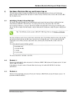
Страница 22: ... Window Kit Window The same information can be found on the sticker on the bottom side of the PCB Most boards will have the identifier and revision printed in plain text as A09 nnnn rr where nnnn is the identifier and rr is the revision Boards with limited space have a sticker with only a data matrix code containing the product identifier revision and serial number The serial number string has the...

Страница 23: ...5 Document Revision History Doc rev Date Comment A 03 2020 Initial document release Document Revision History 2020 Microchip Technology Inc User Guide DS50002956A page 23 ...

Страница 24: ...U203 512k x 8 Ser ial Flash VCC_TARGET GND 100n C208 GND VCC_TARGET PF5_ERR_LED PD1_MBUS_PWM PF4_DATA_LED_DGI BLE ERR PF3_SW0_DGI_FW TP201 PD0_SPI_CS PA5_SPI_MISO PA6_SPI_SCK PA4_SPI_MOSI VCC_TARGET TP207 TP206 TP202 TP204 TP205 PA3 1 EXTCLK PA0 30 PA1 31 PA2 32 PA4 2 PA5 3 PA6 4 PA7 5 PC0 6 PC1 7 PC2 8 PC3 9 PD0 10 PD1 11 PD2 12 PD3 13 PD4 14 PD5 15 PD6 16 PD7 17 AVDD 18 GND 19 TOSC1 PF0 20 TOSC2...

Страница 25: ...3 SW 3 SW 6 FB CFF 11 MIC33050 SYHL U301 100k R305 10uF 10V C302 GND GND VCC_DEBUGGER VCC_TARGET 1 2 CH7410 2032LF J300 VBUS MIC94165 VIN B2 VOUT A1 VIN A2 EN C2 GND C1 VOUT B1 U300 MIC94165 VIN B2 VOUT A1 VIN A2 EN C2 GND C1 VOUT B1 U302 GND GND GND GND 2M R300 VBAT 0R R301 0R R304 1 2 1125 1102S0S113R1 J301 N M 2 1 4 SS G D S 3 MIC94050 Q300 0R R303 1k R306 P3V3_ENABLE VBAT_OUT 2 1 NSR20F30NXT5G...

Страница 26: ...D 28 VDDCORE 29 VDDIN 30 SWDCLK PA30 31 SWDIO PA31 32 SAMD21E18A MUT U100 USBD_P USBD_N 1u C101 VCC_MCU_CORE VCC_DEBUGGER VCC_DEBUGGER GND GND GND GND DBG2 S1_0_TX S0_2_TX DAC VTG_ADC RESERVED S0_3_CLK DBG0_CTRL CDC_TX_CTRL BOOT DEBUGGER POWER STATUS LED 1k R104 DBG1 DBG1_CTRL REG_ENABLE 100k R101 100k R102 SWCLK 100k R109 GND SRST DEBUGGER TESTPOINT DBG2_CTRL CDC_RX_CTRL 100k R106 SWCLK DBG2_GPIO...

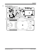
Страница 27: ...0 1 0 1 0 P A J 1 0 1 0 1 1 P A J 1 0 1 0 5 P A J 1 0 1 0 4 P A J 1 0 1 0 3 P A J 1 0 1 0 2 P A J 1 0 1 0 1 P A J 1 0 1 0 0 COJ101 P A J 2 0 0 0 1 P A J 2 0 0 0 2 P A J 2 0 0 0 4 P A J 2 0 0 0 3 P A J 2 0 0 0 7 P A J 2 0 0 0 8 P A J 2 0 0 0 6 P A J 2 0 0 0 5 P A J 2 0 0 0 0 C O J 2 0 0 P A J 2 0 1 0 1 P A J 2 0 1 0 2 P A J 2 0 1 0 4 P A J 2 0 1 0 3 P A J 2 0 1 0 7 P A J 2 0 1 0 8 P A J 2 0 1 0 6 P...

Страница 28: ...upport is available through the website at http www microchip com support Microchip Devices Code Protection Feature Note the following details of the code protection feature on Microchip devices Microchip products meet the specification contained in their particular Microchip Data Sheet Microchip believes that its family of products is one of the most secure families of its kind on the market toda...

Страница 29: ...ASIC Plus ProASIC Plus logo Quiet Wire SmartFusion SyncWorld Temux TimeCesium TimeHub TimePictra TimeProvider Vite WinPath and ZL are registered trademarks of Microchip Technology Incorporated in the U S A Adjacent Key Suppression AKS Analog for the Digital Age Any Capacitor AnyIn AnyOut BlueSky BodyCom CodeGuard CryptoAuthentication CryptoAutomotive CryptoCompanion CryptoController dsPICDEM dsPIC...

Страница 30: ...3 7252 China Xiamen Tel 86 592 2388138 China Zhuhai Tel 86 756 3210040 India Bangalore Tel 91 80 3090 4444 India New Delhi Tel 91 11 4160 8631 India Pune Tel 91 20 4121 0141 Japan Osaka Tel 81 6 6152 7160 Japan Tokyo Tel 81 3 6880 3770 Korea Daegu Tel 82 53 744 4301 Korea Seoul Tel 82 2 554 7200 Malaysia Kuala Lumpur Tel 60 3 7651 7906 Malaysia Penang Tel 60 4 227 8870 Philippines Manila Tel 63 2 ...

Отзывы: