Figure 3-2. Monitoring Debug GPIO with MPLAB Data Visualizer
Debug GPIO channels are timestamped, so the resolution of DGI GPIO events is determined by the resolution of the
DGI timestamp module.
Important:
Although bursts of higher-frequency signals can be captured, the useful frequency range of
signals for which debug GPIO can be used is up to about 2 kHz. Attempting to capture signals above this
frequency will result in data saturation and overflow, which may cause the DGI session to be aborted.
3.1.4.2
Timestamping
DGI sources are timestamped as they are captured by the debugger. The timestamp counter implemented in the
Curiosity Nano debugger increments at 2 MHz frequency, providing a timestamp resolution of a half microsecond.
3.2
Power Supply
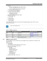
The board can be powered through the USB port or by a CR2032 battery. It will automatically switch to the battery if
USB power is not available. While powered through USB, the board generates 3.3V for the debugger, ATmega3208,
and peripherals. During battery operation, the ATmega3208 and peripherals run directly on the battery voltage, while
the debugger is not powered.
Current drawn from the USB port is limited to 500 mA by a PTC resettable fuse.
Important:
When powering the AVR-BLE board with a CR2032 battery, it is important to leave the
ATmega3208 pins that connect to the CDC UART in Tri-State (Input) mode. This is to prevent the
debugger from getting powered through its GPIO.
Hardware User Guide
©
2020 Microchip Technology Inc.
User Guide
DS50002956A-page 13


