Page 4 of 31. Version 1.03 September 2012
Microbee Premium Plus+ | Construction Manual
If you have not done so already, please take the time to check through the component list &
check off each item to make sure you have everything that you need that is supposed to be
supplied with the kit. We do check every kit for completeness, but mistakes can happen, so
its better that you make sure that it is complete before you start construction.
2.b Preparing the Baseboard PCB
You should have a blank Printed Circuit board labelled 8501-4-0CR (this can be found on the
PCB on the component side, rear, right side, near the 5 Pin DIN socket position).
The PCB has a number of configuration ‘jumpers’ on it where the default position is made by
tracks connecting 2 vias (a ‘via’ is a small plated hole in the board that connects top side
tracks to bottom side tracks).
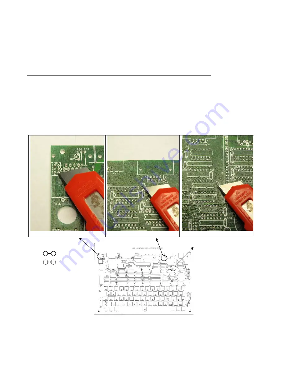
Three of these jumpers have to be cut from their default position and left ‘open’. These are
Jumper W1 position 3 A-B, Jumper W4 1-2 and Jumper W2 1-2 See the diagrams below :
W1 Pos 3 A-B
W4 1-2
W2 1-2
Be very careful when you are making the cuts not to slip and cut another track. It is more
controlled just to ‘take a little divot’ out of the track between the 2 vias, using the sharp
< Before
< After


