Microair Avionics
T2000SFL Transponder
Installation Manual
6.0
WIRING
The T2000SFL must be installed with a wiring harness which meets the following requirements.
6.1
General Wiring
Microair recommends that the encoder be installed and wired in accordance with the manufacturer’s installation
instructions. The encoder can be powered directly from the T2000SFL. The T2000SFL is to be powered from
the aircraft supply, via the avionics master and fuse/circuit breaker with a
maximum
5 amp rating (3 amp
minimum).
IMPORTANT NOTE
The aircraft’s electrical system may produce severe transient voltages
during engine start and stop
Microair recommends that the avionics master be turned off during
engine start and stop, to prevent damage occurring to the T2000SFL.
Damage to the transponder as a result of transient voltages is NOT
covered by the warranty.
It is very important to secure all D series plugs via their security screws before operation. Aircraft vibration may
disconnect a D series plug if it not secured. Where possible, wiring is to be run separately to the coaxial cable.
Microair recommends that wiring for all of the T2000SFL’s functions and connections be run at the time of
installation, even though they may not be required at this stage. Adding additional wiring to the loom at a later
stage may be very difficult. All wiring should be installed in accordance with FAA AC43.13-1A Chapter 11 or
equivalent.
Microair recommends the following cable types for connection of the T2000SFL:
Power Input
18 AWG TEFZEL 22759/16-16
Red and Black Wire
External Connections
22 AWG TEFZEL 22759/16-22
Wire or
22 AWG TEFZEL 27500-22TG1T14
Single core shielded
Encoder Power
22 AWG TEFZEL 22759/16-22
Red and Black Wire
Encoder Data
22 AWG TEFZEL 22759/16-22
White Wire
To ensure correct installation and to make future service simple, Microair recommends that all wiring be
labelled for easy identification.
T2000SFL Installation Manual 01R7-1
Page 9 of 23
25
th
Содержание T2000SFL
Страница 13: ......
Страница 14: ......
Страница 15: ......
Страница 16: ......
Страница 17: ......
Страница 18: ......
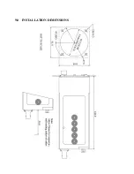
Страница 19: ...9 0 INSTALLATION DIMENSIONS...
Страница 21: ...11 0 PANEL TEMPLATE 61 61 57 67 DIA 4 5mm 45 DEG...
Страница 23: ...13 0 LIMITED WARRANTY...


