Microair Avionics
T2000SFL Transponder
Installation Manual
2.0
PANEL MOUNTING
If standard mounting is desired (no remote display unit), determine a suitable location in the instrument panel in
full view of both pilots. Cut a 57mm diameter (2 ¼ inch) hole with 4 x 4mm holes for the mounting screws.
Dimensions for this are provided on the panel template. Allow a minimum of 63mm (2 ½ inch) square, behind
the cut out, to allow clearance from other instruments. A depth of 180mm (7 inches) is recommended to
accommodate the transponder and electrical connectors.
M4 MACHINE SCREWS
57MM (2 1/4") INSTRUMENT HOLE
NO REAR SUPPORT REQUIRED
MICROAIR T2000 SFL
PANEL INSTALLATION
DB-25 CONNECTOR
WIRING HARNESS
50 OHM
COAX
BNC CONNECTOR
The T2000SFL weights only 600g (1 lbs). The four M4 x 12mm machine screws are sufficient to support the
transponder. No rear support is required unless the panel structure itself is too weak to support the load.
IMPORTANT NOTE
Removal of the chassis screws for the purpose of attaching support
bracket is not permitted.
The drilling of holes in the chassis for any purpose is not permitted.
Filings from changing the thread of the M4 screw may cause electrical
faults. Faults of this type are NOT covered by the warranty.
T2000SFL Installation Manual 01R7-1
Page 5 of 23
25
th
Содержание T2000SFL
Страница 13: ......
Страница 14: ......
Страница 15: ......
Страница 16: ......
Страница 17: ......
Страница 18: ......
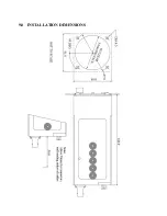
Страница 19: ...9 0 INSTALLATION DIMENSIONS...
Страница 21: ...11 0 PANEL TEMPLATE 61 61 57 67 DIA 4 5mm 45 DEG...
Страница 23: ...13 0 LIMITED WARRANTY...


