background image

Page 65

Operation

induSENSOR DTD / MSC7xxx

5.5.2 

Synchronization and Installation of Multiple Channels

MSC7602 model

If the minimum distance of ≥ 100 mm

, see 5.3

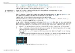
, is impossible, the MSC7602 model in addition offers the 

possibility to synchronize the supply frequency of the sensors. This significantly reduces or eliminates cross-
talking between the channels, which strongly depends on the sensor used and the distance or arrangement 
to one another.
The following prerequisites/restrictions apply for sync operation:

 - All synchronized sensors must be operable with the supply frequency of the master sensor

, see 5.3.3

.

 - In sync mode, no automatic sensor recognition is possible with the slave.
 - In sync mode, the slave channel must be set to the frequency of the master.
 - The synchronization settings are not possible via the sensorTOOL

, see A 3

.

 -

Synchronization is only possible with a frequency response set to ≥ 50 Hz.

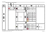
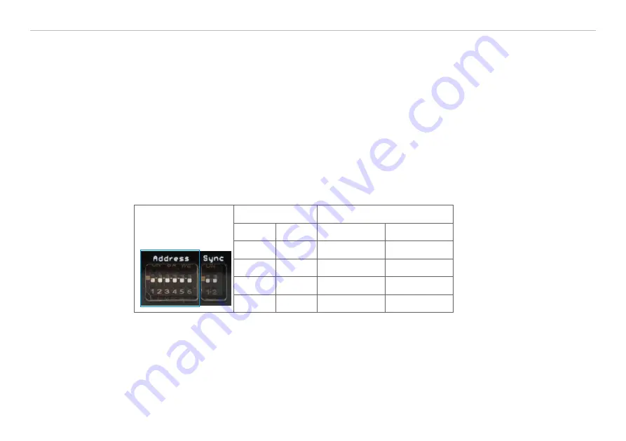
The respective synchronization modes can be set via DIP switches:

Switch setting

Operation

S1

S2

Sensor 1

Sensor 2

off 

1

off 

1

independent

independent

off

on

Master

Slave

on

off

Slave

independent

on

on

Slave

Slave

Fig. 65 DIP switch on the induSENSOR MSC7602 for synchronization

1) Factory settings

Содержание induSENSOR DTD

Страница 1: ...MSC7401 MSC7401 0x0 MSC7802 MSC7802 0x0 MSC7602 DTD Operating Instructions induSENSOR DTD MSC7401 7802 7602...

Страница 2: ...ECHNIK GmbH Co KG Koenigbacher Str 15 94496 Ortenburg Germany Phone 49 0 8542 168 0 Fax 49 0 8542 168 90 e mail info micro epsilon com www micro epsilon com Miniature sensor controller for inductive d...

Страница 3: ...ecautions 15 4 2 Controller 16 4 2 1 DTD Model 16 4 2 2 MSC7401 Model 17 4 2 3 MSC7802 Model 20 4 2 4 MSC7602 Model 23 4 3 Power Supply Sensor and Signal Output DTD LVDT 26 4 4 Power Supply Sensor and...

Страница 4: ...ustment 57 5 4 3 Example A Sensor Parameter Adjustment DTA 5G8 Channel 1 58 5 4 4 Example B Signal Output Adjustment 2 10 V Channel 1 59 5 4 5 Example C Adjustment via Zero point Adjustment Channel 1...

Страница 5: ...point Adjustment 82 A 3 4 Measurement Menu 85 A 3 4 1 Data Acquisition 86 A 3 4 2 Signal Processing 87 A 3 4 3 CSV Output 88 A 3 4 4 Description Data Acquisition Table 89 A 3 5 Single Value Menu 90 A...

Страница 6: ...induSENSOR DTD MSC7xxx...

Страница 7: ...ided Indicates a user action i Indicates a tip for users Measurement Indicates hardware or a software button menu 1 2 Warnings Connect the power supply and the display output device according to the s...

Страница 8: ...n industrial environ ments The EU Declaration of Conformity and the technical documentation are available to the responsible authori ties according to EU Directives 1 4 Intended Use Das induSENSOR DTD...

Страница 9: ...tion class only controller DTD IP67 plugged MSC7401 and 7802 IP67 plugged MSC7602 IP20 Temperature range Operation 40 85 C 40 185 F Storage 40 85 C 40 185 F Humidity 5 95 non condensing Ambient pressu...

Страница 10: ...sors the frequency and the supply voltage can be set see 5 The demodulator electronics transforms the signal of the two secondary coils into the set output signal With the setting possibilities for ze...

Страница 11: ...ble Supply and output cable Any type of half bridge and full bridge sensors can be connected to the amplifier electronics However if sen sors of other manufacturers are used you should check their fun...

Страница 12: ...Ethernet 4 EtherCAT 4 RS485 PROFINET 4 EtherNet IP 4 Analog output 2 5 0 2 10 V 0 5 4 5 V 0 5 V Ra 1 kOhm or 0 4 20 mA load 500 Ohm Connection Supply signal 5 pin M12 plug in connector cable optional...

Страница 13: ...ection Reverse polarity protection overvoltage protection Sensor excitation 7 Preset at factory cannot be changed 550 mVPP 350 mVPP 150 mVPP 75 mVPP 1 2 5 10 13 kHz DTA 9 13 16 21 23 kHz LDR Gain Dete...

Страница 14: ...y remove the components of the measuring system from the packaging and ensure that the goods are forwarded in such a way that no damage can occur Check the delivery for completeness and shipping damag...

Страница 15: ...controller Do not bend more tightly than the minimum bending radius of the cables Damage or destruction of the cables Failure of the measuring device Check all plug in connections for firm seating be...

Страница 16: ...see 3 1 as well as a suitable M3 screw M12x1 17 4 69 dia 9 8 35 28 1 1 10 39 56 2 2 10 39 18 71 dia approx 30 35 1 18 1 38 20 79 8 5 3 3 Ferrite Fig 2 Dimensional drawing of DTD controller dimensions...

Страница 17: ...tion of the mounting holes is shown in the drawing see Fig 4 The tightening torque for the cover screws is 0 9 Nm The maximum tightening torque for the SW15 M12 cable gland is 1 5 Nm and for the SW19...

Страница 18: ...42 1 65 5 5 22 12 47 11 43 21 5 85 76 2 99 25 5 1 0 7 5 29 dia 4 3 17 dia Sensor connection Cable gland WS15 Clamping range 1 mm 5 mm Power and signal connection Cable gland WS19 Clamping range 4 5 m...

Страница 19: ...53 2 09 52 2 04 42 1 65 5 5 22 12 47 11 43 76 2 99 4 3 17 dia 14 5 57 3 1 12 Sensor connection M9 5 pole socket Series 712 Binder Power and signal connection M12x1 plug 5 pole 7 5 29 dia Fig 5 Dimens...

Страница 20: ...position of the mounting holes is shown in the drawing see Fig 6 The tightening torque for the cover screws is 0 9 Nm The maximum tightening torque for the SW15 M12 cable gland is 1 5 Nm and for the...

Страница 21: ...1 35 54 2 13 36 6 1 44 25 5 1 105 4 13 21 5 85 152 5 98 4 3 17 dia 7 5 29 dia Power and signal connection Cable gland WS19 Clamping range 4 5 mm 10 mm Sensor connections Cable gland WS15 Clamping ran...

Страница 22: ...56 105 4 13 4 3 17 dia 7 5 29 dia 15 5 61 4 1 16 124 6 4 90 5 5 22 54 2 13 34 2 1 35 36 6 1 44 Sensor connections M9 5 pole socket Series 712 Binder Power and signal connection M12x1 plug 5 pole Fig 7...

Страница 23: ...plug e g MCVR 1 5 5 ST 3 81 Phoenix 1827156 see A 1 with the bus connector Position the MSC7602 controller on the DIN rail and press it down until it snaps in see Fig 8 2 1 Fig 8 Installation of contr...

Страница 24: ...Page 24 Installation and Assembly induSENSOR DTD MSC7xxx 22 6 89 103 73 4 08 99 3 90 113 65 4 47 29 2 1 15 107 4 21 Fig 10 Dimensions of MSC7602 controller model dimensions in mm inches...

Страница 25: ...guided through a fastening clip with a sleeve shaped ferrite both included in delivery see 3 1 This ferrite must be mounted as close as possible to the input terminals Fastening clips Ferrite Fig 11 I...

Страница 26: ...see A 1 is ten times the cable diameter Connection on power supply output side 5 pin M12x1 housing connector A coded Fig 12 View with plug in connector DTD LVDT Pin Assignment Cable color PC5 5 IWT 4...

Страница 27: ...al output are on the controller see Fig 14 see Fig 15 Connections Power supply output side Cable gland SW19 clamping range 4 5 mm 10 mm Screw terminal connection AWG 16 up to AWG 24 up to AWG 28 with...

Страница 28: ...rimary Sensor cable shield Fig 16 Pin assignment for the sensor at terminal block X2 full bridge Terminal block X2 Pin Cable 1 DTA x CA x DTA x CR x C701 x Braid 1 DTA x LA x Solder pin 1 DTA x TA x C...

Страница 29: ...A LVP 25 20 x Connector LDR x SA Sensor cable 1 C7210 x Shield sensor cable 1 Secondary center tap 2 Green 4 Black Secondary 3 White 1 Brown Secondary 4 Brown 3 Blue Primary 5 Primary 6 Fig 19 Table o...

Страница 30: ...Page 30 Installation and Assembly induSENSOR DTD MSC7xxx 4 4 1 Power Supply and Signal X2 1 2 3 4 1 2 1 2 3 4 5 6 X1 X3 Fig 20 Pin assignment for supply and signal on the terminal blocks X2 X3 X1...

Страница 31: ...4 Black Supply voltage 2 White 1 Brown GND supply signal ground 3 Brown 3 Blue Shield housing 4 Cable shield Cable shield guided over connector 2 White 5 Gray Fig 21 Table for pin assignment of suppl...

Страница 32: ...econdary Sensor pin assignment DTA LVDT Variant with cable gland X2 1 2 3 4 5 6 Connector 1 2 3 4 5 5 pin housing socket M9 Binder series 712 View on pin side Assignment Pin X2 DTA x CA x DTA x CR x C...

Страница 33: ...M9 Binder series 712 View on pin side Assignment Pin X2 LDR x CA LVP 25 Z20 x Cable C7210 x 5 pin Shield 1 Housing Secondary center tap 2 Green Black 5 Secondary 3 White Brown 1 Secondary 4 Brown Blu...

Страница 34: ...s signal output are on the controller see Fig 6 Connections Power supply output side Cable gland SW19 clamping range 4 5 mm 10 mm Screw terminal connection AWG 16 up to AWG 24 up to AWG 28 with ferrul...

Страница 35: ...rimary Sensor cable shield Fig 27 Pin assignment for the sensor at terminal block X2 full bridge Terminal block X2 Pin Cable 1 DTA x CA x DTA x CR x C701 x Braid 1 DTA x LA x Solder pin 1 DTA x TA x C...

Страница 36: ...20 x Connector LDR x SA Sensor cable 1 C7210 x Shield sensor cable 1 Secondary center tap 2 Green 4 Black Secondary 3 White 1 Brown Secondary 4 Brown 3 Blue Primary 5 Primary 6 Fig 30 Table of the pin...

Страница 37: ...R DTD MSC7xxx 4 5 1 Power Supply and Signal Sensor 1 Sensor 2 1 2 3 4 5 6 X2 1 1 2 3 4 5 6 X2 2 Menu Down Enter Up Chan E1 E2 Value X1 6 5 4 3 2 1 X3 D1 D2 D3 D4 Fig 31 Pin assignment for power supply...

Страница 38: ...ut for channel 1 2 Yellow 4 Black Supply voltage 3 White 1 Brown GND supply signal ground 4 Brown 3 Blue 5 5 Gray Shield housing 6 Cable shield Cable shield guided over connector Fig 32 Table for pin...

Страница 39: ...nt Sensor 1 2 DTA LVDT Variant with cable gland Sensor 1 Sensor 2 1 2 3 4 5 6 X2 1 1 2 3 4 5 6 X2 2 Connector 1 2 3 4 5 5 pin housing socket M9 Binder series 712 View on pin side Assignment Pin X2 x D...

Страница 40: ...5 pin housing socket M9 Binder series 712 View on pin side Assignment Pin X2 x LDR x CA LVP 25 Z20 x Cable C7210 x 5 pin Shield 1 Housing Secondary center tap 2 Green Black 5 Secondary 3 White Brown 1...

Страница 41: ...he Sync signal is only available on the DIN rail bus connector and executed in series i e it is not dai sy chained in the bus connector All of the connections for the power supply sensors signal outpu...

Страница 42: ...n Output signal 1 3 Yellow Output signal 2 4 Green Cable shield sensor 2 direct connection to DIN rail 5 Fig 40 Table for pin assignment of supply and analog output Assignment Pin 1 2 3 4 5 Supply vol...

Страница 43: ...2 Fig 43 Terminal block X2 1 Assignment Pin X2 x DTA x CA x DTA x CR x Cable C701 x DTA x CA x DTA xG8 x Secondary center tap 1 Gray Gray Gray Secondary 2 White White Black Secondary 3 Brown Black Wh...

Страница 44: ...y Cable shield sensor 1 2 see X1 and X3 Fig 45 Table for pin assignment sensor 1 2 LDR i Cable lengths 10 m between sensor and controller may impair the technical data see 2 3 4 6 3 Digital Interface...

Страница 45: ...sed i If a sensor is replaced the channel must be re parameterized and readjusted The parameter setup of the controller may either be performed via keys on the controller or via the sensor TOOL see A...

Страница 46: ...at the wiring of the sensor connections signal cable and power supply connections are correct before connecting the controller to the power supply and turning it on see 4 Then switch on the power supp...

Страница 47: ...nsor 1 Sensor 2 1 2 3 4 5 6 X2 1 1 2 3 4 5 6 X2 2 Menu Down Enter Up Chan E1 E2 Value X1 6 5 4 3 2 1 X3 D1 D2 D3 D4 Menu Enter Chan E1 E2 Value Address Sync D1 D2 D3 D4 Fig 48 Controller induSENSOR MS...

Страница 48: ...el with and the channel can be changed red and green Channel 1 green channel 2 red It flashes in corresponding color if the channel is not parameter ized Menu Enter Chan E1 E2 Value Address Sync D1 D2...

Страница 49: ...settings It is divided into four function blocks see Fig 52 The 4 LEDs show the current position in the menu and the corresponding setting value at any time see 5 4 Alternatively the software sensorTO...

Страница 50: ...automatic sensor recognition has been completed the LEDs confirm the status D3 D4 green Sensor recognition successful After successful recognition the system is ready for use The output signal is pre...

Страница 51: ...etting of the sensor parameters the adjustment of the system see 5 3 4 is recommended Sensor model Measuring range Sensor type Supply frequen cy Excitation voltage DTA 1x 1 mm LVDT 5 kHz 550 mV DTA 3x...

Страница 52: ...the measuring range and the corresponding signal values Factory settings The controller can be reset to the parameters stored by default see A 2 Zero point adjustment This is a special case of a two p...

Страница 53: ...f the menu structure 1 O LED orange O LED orange flashing G LED green G LED green flashing R LED red R LED red flashing LED off SMR Start of measuring range MMR Mid of measuring range EMR End of measu...

Страница 54: ...ee Fig 59 ENTER E1 level G Factory settings O Zero point adjust ment G MENU 3 sec Automatic sensor rec ognition ENTER G Successful G Successful E1 level R R Failed R Failed Sensor parameter G Manually...

Страница 55: ...4 Value Next menu R Sensor parameter ENTER R Sensor type G DTA LVDT R LDR ENTER G G Frequency DTA LDR G 1 kHz 9 kHz O 2 kHz 13 kHz R 5 kHz 16 kHz R 10 kHz 21 kHz R O 13 kHz 23 kHz ENTER O Amplitude G...

Страница 56: ...he electrical center of the sensor G R ENTER G R The LED color changes depending on the position of the measuring object O Move the measuring object to position X2 1 and change the output signal V2 wi...

Страница 57: ...til the output has reached V0 Lights orange when the measuring object is in the electrical center of the sensor ENTER G O The LED color changes depending on the position of the measuring object O Move...

Страница 58: ...le A G R R R Output situation sensor is not automatically recognized Press button 2x G R Menu point Sensor Parameter see 5 3 3 ENTER Confirm by pressing the ENTER button G R R G Sensor type LVDT with...

Страница 59: ...n delivery state the electronics works with automatic load recogni tion depending on the output load the LED D4 is red 4 20 mA or orange 2 10 V If the automatic settings suits you you can cancel examp...

Страница 60: ...e arrow keys to set the voltage in such a way that the measuring device displays 6 00 V V0 ENTER Confirm by pressing the ENTER button G G O Now move the measuring object to the zero point X0 MMR where...

Страница 61: ...n or switched off G G Go to the menu Adjustment see 5 3 4 ENTER Confirm by pressing the ENTER button G G G G G R Select two point adjustment ENTER Confirm by pressing the ENTER button G G R Now move t...

Страница 62: ...rating the MSC7401 MSC7602 MSC7802 models multi channel operation is possible i For multi channel operation a distance of at least 100 mm between the respective sensors is recom mended Recommended dis...

Страница 63: ...el 2 address 99 However if the addresses are assigned via the sensorTOOL see Fig 64 the addresses can be set individual ly But channel 1 only allows even address values while channel 2 only allows odd...

Страница 64: ...0 119 OFF OFF ON ON ON ON 111100 122 121 ON OFF ON ON ON ON 111101 124 123 OFF ON ON ON ON ON 111110 126 125 ON ON ON ON ON ON 111111 Fig 64 Address assignment on the induSENSOR MSC7602 1 Factory sett...

Страница 65: ...operation All synchronized sensors must be operable with the supply frequency of the master sensor see 5 3 3 In sync mode no automatic sensor recognition is possible with the slave In sync mode the sl...

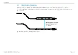
Страница 66: ...nnel 2 Slave Sync signal Sync signal MSC7602 Channel 1 Slave Channel 2 Slave Sync signal Fig 66 Example of synchronization induSENSOR MSC7602 MSC7802 model The MSC7802 offers restricted synchronizatio...

Страница 67: ...send in the affected parts for repair or replacement If the cause of a fault cannot be clearly identified please send the entire measuring system to MICRO EPSILON MESSTECHNIK GmbH Co KG Koenigbacher S...

Страница 68: ...ntenance of the product repairs or modifications by third parties the use of force or other handling by unqualified persons This limitation of liability also applies to defects resulting from normal w...

Страница 69: ...ustrial waste e g residual waste can or the yellow recycling bin and must be disposed of separately This avoids hazards to the environment due to incorrect disposal and ensures proper recycling of the...

Страница 70: ...able length 6 m 4 core open ends with ferrules shielded OD 5 6 mm PC5 5 IWT Power and output cable connector M12x1 5 pin A coding length 5 m 5 core open ends OD 5 6 mm IP 67 IF7001 Single channel USB...

Страница 71: ...integration into PLC with GSDML file certified according to PNIO V2 33 IF2030 ENETIP Interface module for connect ing Micro Epsilon sensors with RS422 RS485 interface to Ethernet IP 1 channel system...

Страница 72: ...unting MCVR 1 5 5 ST 3 81 Phoenix 1827156 A 2 Factory Settings The controller is assigned with the following parameters by default Frequency response 50 Hz only adjustable via sensorTOOL software see...

Страница 73: ...ad software sensorTOOL exe A 3 1 Controller Search Connect the controller to a free USB port of your PC e g via the IF7001 and connect the power supply Start the sensorTOOL program In the drop down me...

Страница 74: ...the serial inter face see Fig 68 click on Start Data Acquisition or on the controller icon see Fig 67 to apply other settings and start the data acquisition see A 3 4 Fig 68 Window Change serial conf...

Страница 75: ...Page 75 Appendix Software induSENSOR DTD MSC7xxx A 3 3 Menu Settings A 3 3 1 General Fig 69 View Settings General...

Страница 76: ...cessful recognition can not be guaranteed on account of tolerances As such the recognition result must always be checked Sensor recognition After switching on the controller automatically identifies t...

Страница 77: ...Page 77 Appendix Software induSENSOR DTD MSC7xxx A 3 3 2 Output Fig 70 View Settings Output Fig 71 Settings Analog output...

Страница 78: ...d is analyzed automati cally after the electronics are switched on Depending on the result 4 20 mA or 2 10 V is output Alternatively you may set the output range manually via the drop down menu see Fi...

Страница 79: ...nu Two point adjustment Zero point adjustment A 3 3 3 1 Two point Adjustment Fig 72 View 1 Two point adjustment Please make sure before the adjustment that the basic settings were carried out sensor c...

Страница 80: ...Software induSENSOR DTD MSC7xxx Then move the target to the desired position X1 Enter the corresponding output value Click Accept X1 Fig 73 View 2 Two point adjustment Repeat this process for the sec...

Страница 81: ...d millimeter values which can be found under Measurement and the additional designation Custom 1 see Fig 78 1 Sensor designation e g DTA 3G8 Custom The chart is divided into 3 areas Green Taught in ra...

Страница 82: ...e adjustment that the basic settings were carried out sensor configuration output signal and that the target can be positioned accordingly Start the sensor adjustment via the Start button Then move th...

Страница 83: ...dix Software induSENSOR DTD MSC7xxx Fig 76 View 2 Zero point adjustment Now move the target inside the midrange to point X2 Also enter the desired output value there and accept it by pressing the butt...

Страница 84: ...point i Optionally you can enter the associated millimeter values which can be found under Measurement and the additional designation Custom 1 The chart is divided into 3 areas Green Taught in range l...

Страница 85: ...Menu To check your measurements a simple data acquisition is available Apply your desired settings before initial operation see A 3 3 Fig 78 View Measurement menu By clicking the Disconnect button you...

Страница 86: ...ing Click the Jump to Head button to display the current signal course A 3 4 1 Data Acquisition Start the data acquisition by clicking the Start button see Fig 80 The acquisition is completely restart...

Страница 87: ...1 Trigger Disabled Deactivated basic settings Continuous Manual trigger One shot sample based Sample can be set records the signal course according to the set samples the more samples the longer the...

Страница 88: ...his button to start acquiring the measurement data Click this button to save the currently selected measurement value Measurement CSV output Format Point Comma Separator Comma Semicolon Tabulator Fiel...

Страница 89: ...urses Mastering By activating the Mastering checkbox you can manually enter the master value Master now in the Measurement Signal Processing menu in the Master tab menu sets the master value see Fig 8...

Страница 90: ...SENSOR DTD MSC7xxx A 3 5 Single Value Menu Fig 85 Single value menu The following settings have an effect on this display Output Analog output see A 3 3 2 Adjustment Two point adjustment see A 3 3 3 1...

Страница 91: ...Fig 86 View Info This window provides the current overview of the controller information sensor information diagnostic infor mation and the currently connected sensor When you click the Disconnect bu...

Страница 92: ...tings for the selected controller to the clipboard By pressing the Factory reset button you can restore the factory settings Export settings opens the explorer to store the setting values in a default...

Страница 93: ...is a serial bus Even if the measured values are output simultaneously in sensorTOOL they are recorded with a time delay To output the data of several bus participants into one graph please proceed as...

Страница 94: ...eturn to the first interactive page after calling sensorTOOL Search Results see Fig 87 Now enable the Multi sensor DAQ mode Then enable the individual checkboxes Use sensor in MULTI DAQ of the respect...

Страница 95: ...Page 95 Appendix Software induSENSOR DTD MSC7xxx In the Data Acquisition menu see A 3 4 the data output of the selected channels is displayed Fig 89 Data Acquisition menu Multi sensor DAQ mode...

Страница 96: ...Page 96 Appendix Software induSENSOR DTD MSC7xxx The Single Value see A 3 5 menu also displays the data as numerical value Fig 90 Single value menu Multi sensor DAQ mode...

Страница 97: ...digital communication A 4 2 Hardware Configuration Transmission technology UART Electrical level RS485 Baud rate 256 000 baud optional 9600 baud Data framing Startbits 1 Databits 8 Parity Even Stopbi...

Страница 98: ...x00 0x00 0x00 0x00 0x00 0x00 0x00 0x00 0x00 0x00 0x00 0x00 0x00 0x2E 0xB2 0x21 0x00 0x00 0x00 0x00 0x00 0x4D 0x53 0x43 0x37 0x34 0x30 0x31 0x20 0x20 0x20 0x20 0x20 0x20 0x20 0x20 0x20 0x20 0x20 0x20 0...

Страница 99: ...sary This can be done by sending the reset message or by disconnecting the controller from power supply 1 DA 126 5 DA new 124 2 SA 1 3 CH Checksum Send Bytes 5 13 4 A 4 4 3 Reset Send 0x68 0x09 0x09 0...

Страница 100: ...mat Example Unscaled value Bytes 8 11 4 bytes float little endian 0x3F6147AE float 0 88 V Scaled value Bytes 12 15 4 bytes float little endian If this value is 0 the cont roller was not set up Otherwi...

Страница 101: ...Page 101 Appendix Communication via RS485 Digital Interface induSENSOR DTD MSC7xxx...

Страница 102: ...Koenigbacher Str 15 94496 Ortenburg Germany Tel 49 0 8542 168 0 Fax 49 0 8542 168 90 info micro epsilon com www micro epsilon com Your local contact www micro epsilon com contact worldwide X9751377 B...

Отзывы: