


Page 40
Installation and Assembly
induSENSOR DTD / MSC7xxx
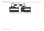
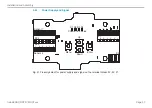
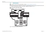
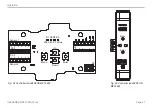
Pin assignment
Sensor 1 + 2 (LDR)
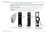
Variant with cable gland
Sensor 1
Sensor 2
1
2
3
4
5
6
X2-1
1
2
3
4
5
6
X2-2
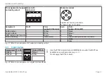
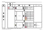
Connector
1
2
3
4
5
5-pin housing socket M9
(Binder, series 712)
View on pin side
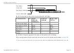
Assignment
Pin X2-x
LDR-x-CA
LVP-25-Z20-x
Cable
C7210-x
5-pin
Shield
1
-
-
Housing
Secondary center tap 2
Green
Black
5
Sec
3
White
Brown
1
Secondary -
4
Brown
Blue
2
P
5
-
-
3
Primary -
6
-
-
4
Fig. 35 Table for pin assignment of sensor (LDR)
i
Cable lengths ≥ 10 m between sensor and controller may impair the technical data
.


