Page 42
Installation and Assembly
induSENSOR DTD / MSC7xxx
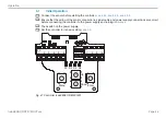
4.6.1
Power Supply and Signal
Assignment
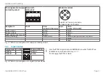
Pin X1 Color (cable: PC7400-6/4)
X1
X2-2
5 4 3 2 1
5 4 3 2 1
Supply v24 V
1
White
GND supply/signal ground
2
Brown
Output signal 1
3
Yellow
Output signal 2
4
Green
Cable shield sensor 2
(direct connection to DIN rail)
5
-
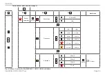
Fig. 40 Table for pin assignment of supply and analog output
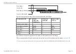
Assignment
Pin
1 2 3 4
5
Supply v24 V
1
Ground 0 V
2
RS485 A
3
RS485 B
4
Sync-signal
5
ME22,5 TBUS 1,5/4P1S KMGY
(Phoenix: 2201732)
Suitable mating plug: MCVR 1.5/5-ST-3.81
(Phoenix: 1827156)
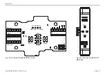
Fig. 41 Table for pin assignment of DIN rail bus connector


