background image

Instructions GD0 21

5.2 

Optional Accessories

In addition to the devices featured in GD0, other ones are available as
optional accessories designed to enhance the automation system and
improve its safety and performances.

GA1:

OSCILLATING ARM accessory that enables the system to open

overhead-type doors

GU1:

MANUAL RELEASE KIT accessory that enables the manual open-

ing of the door even in the event of power failures.

For information on the new accessories, refer to the MHOUSE catalogue
or visit the site www.mhouse.biz.

5.3 

Adding or Removing Devices

Devices can be added to or removed from the GD0 automation system
at any time. 

Do not add any devices until you have made sure that they are
perfectly compatible with GD0; for further information contact
MHOUSE Customer Service.

5.3.1 

Phototest output

This control unit is equipped with the “Phototest” function that increases
the reliability of the safety devices, making it possible to achieve “cate-
gory 2” according to the EN 954-1 (edit. 12/1998) regarding the control
unit and safety photocells.    

Whenever a manoeuvre is begun, the relative safety devices are checked
and only if everything is in order will the manoeuvre start. If the test has
a negative outcome (photocell blinded by the sun, short-circuited cable
etc.), the fault is recognised and the manoeuvre is not performed.   

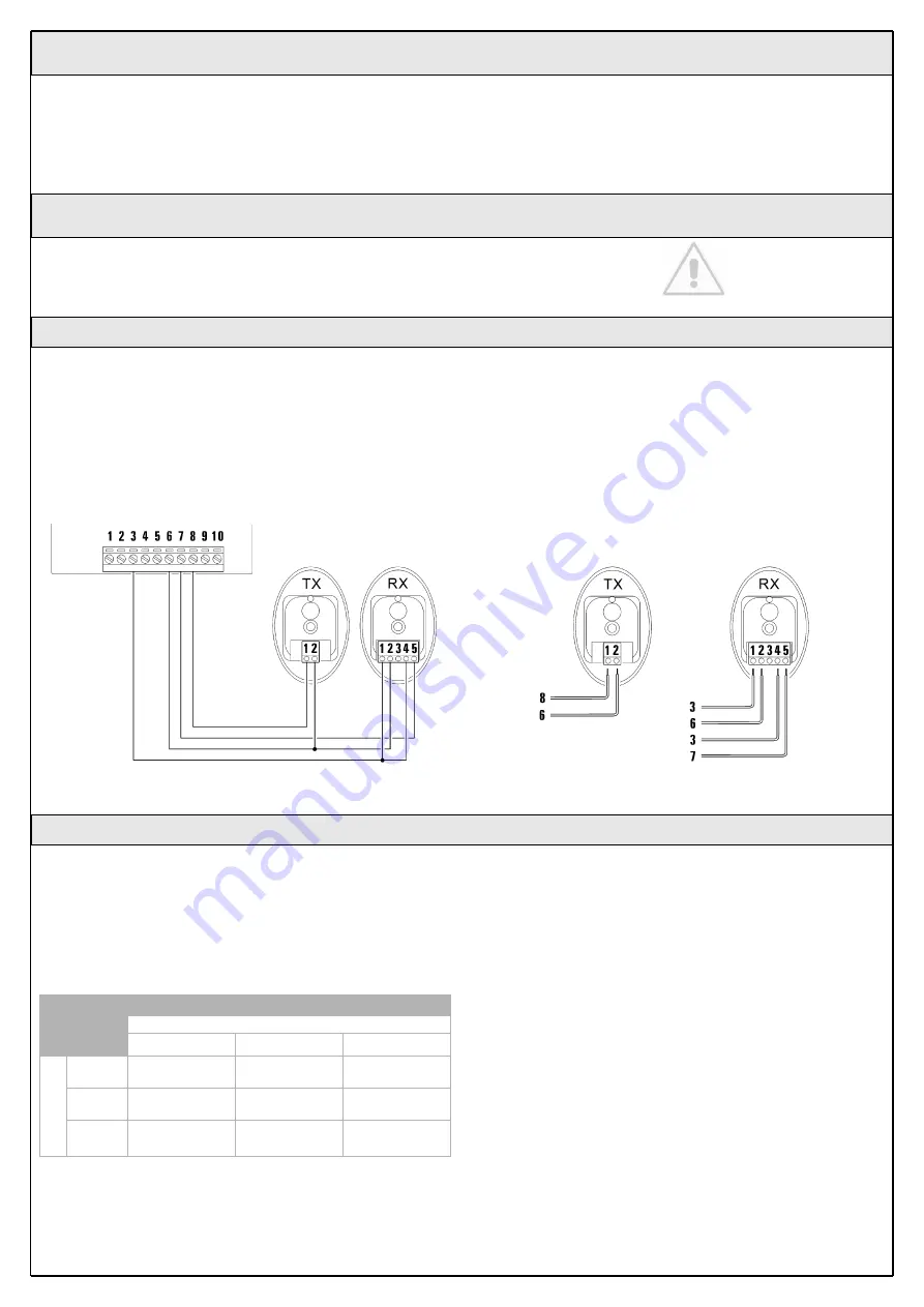
To add a pair of photocells, remove the jumper and connect as follows.

The photocell transmitter power is taken between terminals 8-6 of the
“Phototest” output and not from the services output. The maximum cur-
rent that can be used on the “Phototest” output is 100mA.  

Activate the synchronism as described in the Photocell instructions, in
the event there are two pairs of photocells that could interfere with one
another.

5.3.2 

STOP Input

STOP is the input that causes the immediate interruption of the manoeu-
vre (with a short reverse run). Devices with output featuring normally
open “NO” contacts (like the KS1 selector switch) and devices with nor-
mally closed “NC” contacts, as well as devices with 8.2K

constant

resistance output, like sensitive edges, can be connected to this input.
Multiple devices, even of different type, can be connected to the STOP
input if suitable arrangements are made.

To do this, proceed as described in the following table:

Note 1. The NO and NC combination can be obtained by placing the two
contacts in parallel, and placing in series to the NC contact an 8.2K

resistance (therefore, the combination of 3 devices is also possible: NO,
NC and 8.2K

).

Note 2. Any number of NO devices can be connected to each other in
parallel.

Note 3. Any number of NC devices can be connected to each other in
series.

Note 4. Only two devices with 8.2K

constant resistance output can be

connected in parallel; if needed, multiple devices must be connected “in
cascade” with a single 8.2K

termination resistance.

Warning: if the STOP input is used to connect devices with safe-
ty functions, only the devices with 8.2K

constant resistance out-

put guarantee the fail-safe category 3.

During the recognition stage of the opening and closing positions of the
door, the control unit recognizes the type of device connected to the
STOP input; subsequently it commands a STOP whenever a change
occurs in the recognized status.

Table 9

1

st

device type:

NO

NC

8,2k

2

nd

device type:

NO

In parallel
(note 2)

(note 1)

In parallel

NC

(note 1)

In series 
(note 3)

In series 

8,2k

In parallel

In series 

not permitted 
(note 4)

Figure 69

Figure 70

Содержание GD0

Страница 1: ...Installation instructions and warnings English IST GD0 GB 4865 Rev 00 del 15 03 2005 MhouseKit GD0 For the automation of a sectional or overhead door...

Страница 2: ......

Страница 3: ...ent that liquid substances have penetrated inside the automation devices immediately disconnect the power supply and contact the MHOUSE customer service department The use of GD0 in these conditions c...

Страница 4: ...stops E GD0K gearmotor 2 2 Description of the automation A B Figure 1 2 Product description 2 1 Applications GD0 is a set of components designed for the automation of sectional or overhead doors in re...

Страница 5: ...of devices GD0K is an electromechanical gearmotor consisting of a 24V direct cur rent motor It features a mechanical release mechanism with cord that allows you to move the door manually in the event...

Страница 6: ...nits The transmission of the command is confirmed by the LED A an eyelet B allows them to be hung on a keyring Figure 7 B A The pair of PH0 wall mounted photocells once they are connected to the contr...

Страница 7: ...e guide and the brackets to the ceiling The head of the guide will have to bear all the strain of opening and closing the door the ceiling mounted brackets will have to bear all the weight of GD0 In b...

Страница 8: ...m 7 2m2 max width max imum torque 55kg Overhead garage doors 240cm max height 270cm 6 48m2 max width maximum torque 55kg The shape of the door and the climatic conditions e g presence of strong wind m...

Страница 9: ...ces refer to figure 13 you can start preparing the conduits for the electrical cables connecting the devices to the control unit The shock resistant conduits are designed to protect the electrical cab...

Страница 10: ...and related washer as in fig 18 7 Hook the upper carriage E to the lower carriage C and place the entire carriage assembly inside the guide as in fig 19 8 Assemble the Guide B head as in fig 20 This...

Страница 11: ...d lift the guide from the front and secure it with two screws anchors or riv ets depending on the type of surface 3 Secure the mounting brackets L using the screws M and nuts N and choosing the hole t...

Страница 12: ...all the strain resulting from opening and clos ing the door 9 Loosen the screws in the two mechanical stops then place the front mechanical stop O before the carriage Figure 33 Push the carriage hard...

Страница 13: ...he edge of the door With sectional doors the photocells can be mounted outside whereas with overhead doors they can only be mounted inside outside they would obstruct the movement of the door Point tr...

Страница 14: ...the hole for the passage of the cables in the bottom or side depending on the installation position using a screwdriver 5 Mark the drilling points using the bottom as reference and make sure that the...

Страница 15: ...ove the small piece of wire between ter minals 3 and 7 and make the connections as in Fig 56 if using the flashing light aerial remove the piece of wire which is con nected to terminal 2 and connect t...

Страница 16: ...ly an external aerial can be used or the small piece of wire that is already connected to the terminal can be left which acts as an aerial 3 4 OPEN input for manoeuvre control devices Normally Open ty...

Страница 17: ...t manoeuvres are not interrupted by any commands If the manoeuvres are not completed repeat the recognition procedure starting from step 1 The position recognition stage can be repeated at any time in...

Страница 18: ...en carefully observed 2 Using the selector switch if provided or the radio transmitter test the opening and closing of the door and make sure that the door moves in the intended direction The test sho...

Страница 19: ...directions provided in the corre sponding maintenance schedule 4 Maintenance 3 7 2 Commissioning The commissioning operations can be performed only after all the tests have been successfully carried...

Страница 20: ...force OPEN function 1 Open Stop Close Stop Press button T2 once 2 Open Stop Close Open Press button T2 twice 3 Open Open Open Open opening only Press button T2 three times The following chapters descr...

Страница 21: ...as described in the Photocell instructions in the event there are two pairs of photocells that could interfere with one another 5 3 2 STOP Input STOP is the input that causes the immediate interruptio...

Страница 22: ...n partially Open only and Close only can be associated to each button In Mode 2 each button requires a separate memorization stage 1 Press button P1 figure 71 on the control unit as many times as the...

Страница 23: ...ion stage or in case of failure Table 10 Symptoms probable cause and possible solution The radio transmitter does not emit any sig nal the LED A does not light up Check to see if the batteries are exh...

Страница 24: ...s pause 2 flashes Triggering of a photocell At the starting of the manoeuvre one or more photocells do not enable it check to see if there are any obstacles If there is an obstacle impeding the movem...

Страница 25: ...tion in progress On Memorization in Mode 1 This is normal during memorization in mode 1 which lasts maximum 10s Series of quick flashes from 1 to 4 Memorization in Mode 2 This is normal during memoriz...

Страница 26: ...r 200W Insulation class 1 a safety grounding system is required Emergency power supply Flashing light output For visual signalling devices with 12V lamp maximum 21W Courtesy light 12V lamp maximum 21...

Страница 27: ...ontrol units Lamp 12V 21W BA15 socket automotive type lamp Power supply contacts The device can only be connected to the FLASH output terminals 9 10 and ARIEL input 1 2 of the MHOUSE automation contro...

Страница 28: ...Operating ambient temperature 20 50 C Use in acid saline or potentially explosive atmosphere No Protection class IP40 suitable for use indoors or in protected environments Dimensions weight 72 x 31 h...

Страница 29: ...L of 9th March 1999 concerning radio equipment and telecommunications terminal equipment and mutual recognition of their conformity According to the following standards ETSI EN 300 220 3 ETSI EN 301 4...

Страница 30: ......

Страница 31: ...nufacture Location address Satisfies the essential requirements of the following Directives 98 37 EC Machine Directive 89 336 ECC Electromagnetic Compatibility Directive 73 23 ECC Low Voltage Directiv...

Страница 32: ......

Страница 33: ...control or key operated selector switch If the safety devices enable the operation the door will open normally otherwise actuate the control again within 3 seconds and keep it actuated 2 After approx...

Страница 34: ...balanced door could cause injury If the range of the remote control is significantly diminished and the light emitted by the LED is feeble the remote control battery is probably exhausted The remote c...

Страница 35: ......

Страница 36: ...Mhouse Via Pezza Alta 13 Z I Rustign 31046 Oderzo TV Italia Tel 39 0422 20 21 09 Fax 39 0422 85 25 82 info mhouse biz www mhouse biz...

Отзывы: