28
SERVICE
LIGHTING
Switch off the wheelchair and pull out
the main fuse (A, Fig. 5) before replac-
ing a defective bulb (Fig. 40).
Headlight setting
The headlights should be set in such a
way that the light cone is visible on the
road. – The lower edge of the light
cone should be set at distance of 3 me-
ters to the front of the wheelchair.
Tools: screwdriver
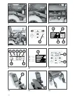
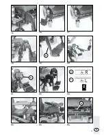
– Loosen the fastening screws (A, Fig
47) and
– set headlights.
– tighten fastening screws.
Replacing a headlight bulb
Filament bulb:
24V/3W E10
Tools: Phillips screw driver
Removal:
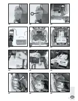
– Loosen the fastening screw and re-
move the lens cover (Fig. 48).
– pull the socket with bulb out of the
lens.
– Unscrew the faulty bulb from the
socket, (Fig. 49).
Mounting:
– Screw the new bulb in the socket,
(Fig. 49). – The earth wire is posi-
tioned above the thread of the sock-
et.
– Place the socket with bulb in the lens.
– Mount the lens, (Fig. 47). – First in-
sert the top pins, then press the lens
downwards and screw into place.
Back light
Filament bulb:
Festoon bulb 24 V/C5W S8.5
Tools: Phillips screw driver
Removal:
– Loosen the fastening screws and re-
move the lens cover (Fig. 52).
– Press the faulty bulb against a holding
frame and remove.
Mounting:
– Insert a new bulb. – Place one tip
into one hole on the fixture, then the
other tip into the other hole (Fig. 52).
– Mount the lens. – First insert the top
pins (Fig. 53), then press the lens
downwards and screw into place.
Front indicator
Ball lamp:
24V/10W BA15s
Tools: Phillips screw driver
Removal:
– Loosen the fastening screw and re-
move the lens cover (Fig. 50).
– Press the faulty ball lamp slightly in-
wards, turn and remove from the
socket.
Mounting:
– Insert a new ball lamp. – Push the
side pins (bayonet catch) into the
frame, exert slight pressure against
the spring and turn until the bayonet
catch clicks into place (Fig. 50).
– Mount the lens. – First insert the top
pins (Fig. 51), then press the lens
downwards and screw into place.
Rear indicator
Ball lamp:
24V/21W BA15s
Tools: Phillips screw driver
Removal:
– Loosen the fastening screws and re-
move the lens cover (Fig. 52).
– Press the faulty ball lamp slightly in-
wards, turn and remove from the
socket.
Mounting:
– Insert a new ball lamp. – Push the
side pins (bayonet catch) into the
frame, exert slight pressure against
the spring and turn until the bayonet
catch clicks into place (Fig. 52).
– Mount the lens. – First insert the top
pins (Fig. 53), then press the lens
downwards and screw into place.
Содержание SPRINT GT 2.593
Страница 38: ...38 SPRINTGT MODELL2 593 1 3 2 1 4 5 6 7 8 9 1a 10 11 12 13 16 15 14...
Страница 39: ...39 2 Abb 2a 2b 30 39 29 37 23 36 40 37 38 32 33 31 35 34 26 25 27 23 24 29 28 37 30 41 27 42 MODE...
Страница 40: ...40 A 3 4 6 7 9 12 13 5 8 11 14 10 34 37 27 B 30 30 4 100 3 75 2 50 1 25 27 MODE 41 35 29 27 36 37 40 27 38 34 A...
Страница 41: ...41 A 15 16 18 19 21 22 24 25 17 20 23 26 R L A A...
Страница 42: ...42 A 28 30 32 33 37 31 34 27 29 35 36 B A C h...
Страница 43: ...43 44 46 39 41 42 40 43 38 45 47 48 49 A A...


