


19
Mechanically height-adjust-
able legrests, code 91
(Fig.20)
!
Attention:
Do not reach into the adjustment
mechanism. – Danger of crushing!
Benefits:
– Adjustment to accommodate stiff
joints, e.g. in the case of a knee inju-
ry, through plaster splint.
– Reduction of the seat pressure. –
Through shift of weight.
– Optimal relaxation of the muscles. –
Through continuous adjustment.
Handling:
– Switch off the wheelchair and move
the brake release lever to the "drive"
position. – This prevents the wheel-
chair from rolling away accidentally.
– Sit in the wheelchair and ask a help-
er to lift the legrest to the required
level (Fig.20).
– To lower the legrest take the pres-
sure off for a moment by lifting the
lower leg (helper) and then pressing
the operating lever forward (A,
Fig.21).
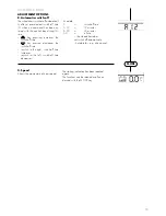
Electrically height-adjustable
legrest, code 86
(Fig.22)
!
Attention:
Do not reach into the adjustment
mechanism. –
Danger of crush-
ing!
Height adjustment
– Switch off the wheelchair and move
the brake release lever to the "drive"
position. – This prevents the wheel-
chair from rolling away accidentally.
– Whilst sitting in the wheelchair, raise
or lower the legrest (Fig.22) to the
desired height via the control box. –
Select the corresponding function
(Fig. 23) by pressing the MODE key.
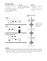
Right legrest angle (R)
– Joystick to the right, legrest swivels
upwards (60° max.).
– Joystick to the left, legrest swivels
downwards.
Left legrest angle (L)
– Joystick to the right, legrest swivels
upwards (60° max.).
– Joystick to the left, legrest swivels
downwards.
Adjusting the length of the
legrests
The legrests can be adjusted via a tele-
scopic tube.
Benefits:
– Individual adjustment of the legrest to
the length of your lower leg
Handling:
Tools:
1x hexagonal stud wrench (width 6 mm)
– Switch off the wheelchair and move
the brake release lever to the "drive"
position. – This prevents the wheel-
chair from rolling away accidentally.
– Loosen adjustment screw (A, Fig.
19).
– Extend the lower part of the legrest
with footrest (6) to the desired
length.
!
Attention:
Only extend the legrest as far as the
guiding mark!
• Observe minimum insertion depth of
5 cm (10 cm for Code 91).
– Tighten the adjusting screw (A, Fig.
19)
Содержание SPRINT GT 2.593
Страница 38: ...38 SPRINTGT MODELL2 593 1 3 2 1 4 5 6 7 8 9 1a 10 11 12 13 16 15 14...
Страница 39: ...39 2 Abb 2a 2b 30 39 29 37 23 36 40 37 38 32 33 31 35 34 26 25 27 23 24 29 28 37 30 41 27 42 MODE...
Страница 40: ...40 A 3 4 6 7 9 12 13 5 8 11 14 10 34 37 27 B 30 30 4 100 3 75 2 50 1 25 27 MODE 41 35 29 27 36 37 40 27 38 34 A...
Страница 41: ...41 A 15 16 18 19 21 22 24 25 17 20 23 26 R L A A...
Страница 42: ...42 A 28 30 32 33 37 31 34 27 29 35 36 B A C h...
Страница 43: ...43 44 46 39 41 42 40 43 38 45 47 48 49 A A...