background image

7 ND90 71 en

21

4.5.1 Remote mounting

ND9100H,ND9100F, ND9100P, ND7100H

For applications if there is e.g.  heavy vibrations, environ-
ment temperature is very high or access is difficult, there is
available remote position measurement option. In this kind
of applications position sensor is attached to actuator and
ND9000 can be installed further away.  Pneumatic piping
between ND9000 and actuator is done as explained in
chapter 4.6 and wiring between position sensor and
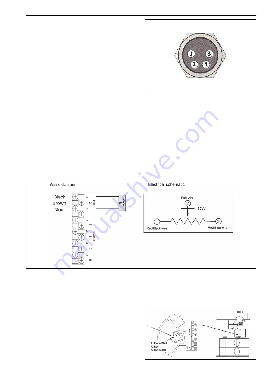
ND9000 according to Fig. 13. 

There are three different cable lengths available between
ND9000 and remote position sensor:  1.2m, 3m and 30m.

If  position  sensor  is  remote  mounted  to  linear  actuator,
there are some parameters which have to be defined as fol-
lowing:

valve acting type (VTYP) have to be defined as rotary

valve rotation direction (ROT) have to be defined as
Clockwise to Close (CC)

Remote position sensor for rotary actuators is available also
with limit switch.

Fig. 14

Pin assignment in female connector view (connec-
tor in device)

Pin assignement

Pin# Function

Cable Shield Ground  (Ground)

2

Potentiometer Plus  (Blue)

3

Potentiometer Center  (Brown)

4 Potentiometer 

Minus 

(Black) 

4.5.2 Quartz position sensor connections and calibration


Potentiometer Calibration

1.

Operate the actuator to the desired “zero” position.
Connect an ohm meter across the terminals POT 1 &
POT 2 to measure the potentiometer output.

2.

Loosen the bottom set screw and rotate the coupling
until the ohm meter reads approximately 5k Ohms
(assuming a 10K Ohm potentiometer). Retighten the
set screw and verify the ohm meter still reads
approximately 5k Ohms.

3.

Operate the actuator to the desired “100 %” position
(assuming 90 degree rotation) and verify the ohm
meter reads (2.7K Ohms or 7.7K Ohms +/- 10 %,
depending on rotation direction).

4.

Remove all test equipment.

5.

Connect the position sensor cable to the terminal
strip as shown in the above wiring diagram.

6.

Connect the connector end of the position sensor
cable to the ND9000 female connector shown in
Fig. 13.   

Содержание neles ND7000H

Страница 1: ...INTELLIGENT VALVE CONTROLLER ND7000H ND9000H ND9000F ND9000P Rev 4 0 Installation Maintenance and Operating Instructions 7 ND90 71 en 5 2019 ...

Страница 2: ...24 5 3 Configuration menu 24 5 4 Mode menu 24 5 5 Configuration parameters 26 5 6 Valve travel calibration 28 5 7 Special displays 30 5 8 Write protection 31 6 MAINTENANCE 32 6 1 Prestage 32 6 2 Spool valve 32 6 3 Flame arrestor assembly 33 6 4 Diaphragms 33 6 5 Communication board 33 7 ERROR MESSAGES 34 7 1 Failsafe errors 34 7 2 Alarms 34 7 3 Errors 34 7 4 Warnings 35 7 5 Notifications 36 8 TROU...

Страница 3: ...ws the ND9000 to be integrated with other field devices to give an unprecedented level of controllability FDT based and DD eEDD multi vendor support con figuration files from download page www metso com ND9000 1 1 7 ND9000 in fieldbus networks Approved interoperability Host interoperability ensured FOUNDATION fieldbus ITK version 6 1 2 certified Profibus PA profile version 3 0 PNO certified Easy t...

Страница 4: ...on Instructions for the Metso ND9000 and ND7000 intelligent valve controller The ND9000 and ND7000 may be used with either cylinder or diaphragm type pneumatic actuators for rotary or linear valves 2 2 Technical description ND9000H and ND7000H The ND9000H and ND7000H are a 4 20 mA loop powered microcontroller based intelligent valve controllers The devices operate even at 3 6 mA input signal and c...

Страница 5: ... ND9000 AND ND7000 INTELLIGENT VALVE CONTROLLER General Either loop powered ND9000H and ND7000H or bus powered ND9000F and ND9000P no external power supply required Suitable for rotary and sliding stem valves Actuator connections in accordance with VDI VDE 3845 and IEC 60534 6 standards Action Double or single acting Travel range Linear 10 120mmwithstandardIECparts Larger strokes possible with sui...

Страница 6: ...s Bus voltage 9 32 V DC reverse polarity protection Quiescent Current Draw 16 mA Max basic current 17 2 mA Fault current FDE 3 9 mA FOUNDATION fieldbus function block execution times ND9000F AO 20 ms AI 20 ms PID 20 ms DO 20 ms DI 15 ms IS 15 ms OS 15ms Performance with moderate constant load actuators Values at 20 C 68 F and without any additional instru ments such as boosters or quick exhaust va...

Страница 7: ... T5 T6 Gb Input Ui 28 V Ii 120 mA Pi 1 W Ci 22 nF Li 53 μH Output Ui 28 V Ii 120 mA Pi 1 W Ci 22 nF Li 53 μH ABNT NBR IEC 60079 0 2013 ABNT NBR IEC 60079 11 2009 IEC 60079 15 2012 ABNT NBR IEC 60079 27 2010 ABNT NBR IEC 60529 2005 Ex nA IIC T4 T5 T6 Gc Input Ui 30 V Ii 152 mA Output Ui 30 V Ii 152 mA Ex ic IIC T4 T5 T6 Gc Input Ui 30 V Ii 152 mA Pmax device limits itself Ci 22 nF Li 53 μH Output U...

Страница 8: ...2008 2009 ABNT NBR IEC 60079 27 2010 Ex ia IIC T4 T5 T6 Ga Ex ia IIC T4 T5 T6 Gb Ui 24 V Ii 380 mA Pi 5 32 W Ci 5 nF Li 10 μH Comply with the requirements for FISCO field device ABNT NBR IEC 60079 0 2008 2011 ABNT NBR IEC 60079 11 2009 IEC 60079 15 2010 ABNT NBR IEC 60079 27 2010 ABNT NBR IEC 60529 2009 Ex nA IIC T4 T5 T6 Gc Ui 24 V Ex ic IIC T4 T5 T6 Gc Ui 32 V Ii 380 mA Pi 5 32 W Ci 5 nF Li 10 μ...

Страница 9: ...e in the worst case Damage to the equipment and personal injury may result CAUTION ND9000 ND7000 Do not remove or dismantle a pressurized controller Removing or dismantling a pressurized prestage or spool valve of an ND leads to uncontrolled pressure release Always shut off the supply air and release the pressure from the pipelines and equipment before remov ing or dismantling the controller Other...

Страница 10: ...sic Safety Ex i WARNING ND9100 ND9200 ND9300 and ND7100 Ensure that the complete installation and wiring is intrinsically safe before operating the device The equipment must be connected via a certified Zener barrier placed outside the hazardous area Ex WARNING ND9200 ND7200 Electrostatic charge hazard The windows and identification plate are non conductive Clean with a damp cloth only Ex WARNING ...

Страница 11: ...rom all actuator connec tions Mount the metal plugs 54 with sealant to the unused controller connections at the bottom of the controller Mount the valve controller loosely to the mounting bracket guiding the pin on the actuator stem to the slot of the feedback arm Align the bracket and the valve controller with the actuator stem and adjust their position so that the feedback arm is approximately a...

Страница 12: ...s with previ ous steps Check that the actuator pin does not touch the valve controller case throughout the entire stroke of the actuator If the actuator pin is too long it may be cut to size Apply grease Molykote or equivalent to the contact surfaces of the actuator pin and the feedback arm to reduce wear 4 4 Piping Table 4 provides the recommended tube sizes in accord ance with actuator sizes Tub...

Страница 13: ...g Air s Spring s Piping Air s Spring s Piping Air s Spring s 1C 0 62 37 3 8 10 mm or 3 8 6 mm or 1 4 x 10 mm or 3 8 6 mm or 1 4 x 1 2 2 1 2C 1 08 66 3 8 10 mm or 3 8 2 4 3 0 3C 2 18 133 3 8 10 mm or 3 8 4 8 5 2 4C 4 34 265 3 8 10 mm or 3 8 3 2 3 7 5C 8 7 531 3 8 10 mm or 3 8 7 5 11 0 6C 17 5 1068 3 4 10 mm or 3 8 12 0 20 0 Air supply piping 10 mm or 3 8 for all actuators Pipe sizes are nominal i e...

Страница 14: ...t signal to close valve not recommended Default setting DIR CLO ROT cC close valve to clockwise ATYP 1 A PFA CLO must be in the spring direction A0 CUTL and VTYP according to valve type 4 Increasing input signal to close valve shown Default setting DIR CLO ROT cC close valve to clockwise ATYP 2 A PFA OPE A0 CUTL and VTYP according to valve type 3 8 Increasing input signal to open valve not recomme...

Страница 15: ...ing to valve type 3 Self closing Default setting ROT cC close valve to clockwise ATYP 1 A PFA CLO must be in the spring direction A0 CUTL and VTYP according to valve type 4 Self opening Default setting ROT cC close valve to clockwise ATYP 1 A PFA OPE must be in the spring direction A0 CUTL and VTYP according to valve type 1 DOUBLE ACTING ACTUATOR REVERSED PIPING Self opening Default setting ROT cC...

Страница 16: ...IEC 61158 2 The same bus cable is used also for the fieldbus communi cation The bus cable is led through a M20 x 1 5 cable gland or 1 2 NPT cable gland U E2 Connect the conductors to the terminal strip as shown in Fig 10 Reverse polarity protection permits connection of the bus cables in any order The cable shield can be grounded by connecting the shield to the earth connection screw The shield ca...

Страница 17: ... screen of the cable is connected to earth either at the barrier dotted line or at the earthing terminal inside ND9000H enclosure dash line If the screen is connected to earth at both ends of the cable the potential equalization of the system shall conform to requirements of IEC 60079 14 2013 Clause 16 2 3 2 X10² terminal 1 SHD does not have any electrical connection If wanted cable screens can be...

Страница 18: ...e with Canadian Electrical Code Part I U S installations should be in accordance with Article 504 in the National Electrical Code ANSI NFPA 70 7 See user manual for installation conditions 8 See documents F41446 and F41476 for the approved switches and their entity parameters 9 Remote Mount option R is only available for ND91_ standard enclosure variants N O I T A C O L S U O D R A Z A H N O I T A...

Страница 19: ...barrier dotted line or at the earthing terminal inside ND9000F P enclosure dash line If the screen is connected to earth at both ends of the cable the potential equalization of the system shall conform to requirements of IEC 60079 14 2013 Clause 16 2 3 2 X10² terminal 3 SHD does not have any electrical connection If wanted cable screen can be connected to this terminal for floating termination of ...

Страница 20: ...HAZARDOUS LOCATION Control system Uout max 30 V Control system Uout max 30 V ND9200H_T ND7200H_T Position Transmitter NONHAZARDOUS LOCATION HAZARDOUS LOCATION ND9200F ND9200P NONHAZARDOUS LOCATION Entity Parameters Ui 32 0 V Entity Parameters Uo Ui connect the cable shield to earth ground Associated apparatus ...

Страница 21: ...tors is available also with limit switch Fig 14 Pin assignment in female connector view connec tor in device Pin assignement Pin Function 1 Cable Shield Ground Ground 2 Potentiometer Plus Blue 3 Potentiometer Center Brown 4 Potentiometer Minus Black 4 5 2 Quartz position sensor connections and calibration Potentiometer Calibration 1 Operate the actuator to the desired zero position Connect an ohm ...

Страница 22: ...ication Then connect the individual wires as shown in connection diagram 2 Connect positioner control 4 20mA signal directly to ND or alternatively to Pass through terminals IN IN and Metso ND9 control input cable to OUT OUT 4 20mA Pass Through connectors positive ter minals are internally shorted and negative ter minals are internally shorted 3 Connector with 24V and GND shall be supplied from ex...

Страница 23: ... unit selection on the top row of the display You may change the selection by pressing or key while keeping the key pressed down When the buttons are released the current selection will be activated If the device has been idle for 1 hour and there is no user activity on the local user interface the measurements will start scrolling on the display This enables the user to view all the measurements ...

Страница 24: ...anised in a menu structure To enter the menus press and keys simultaneously in the measurement monitoring view panel To move to the next or previous selection by pressing or key accord ingly 5 4 Mode menu If the user wants to change the valve operating mode press the key at the MODE selection The MODE will start to flash and by pressing or key you may alter the opera tion mode selection User accep...

Страница 25: ...change the manual setpoint return to the measurement monitoring view and go to target position measurement Press the key shortly to activate the tar get position editing text TPOS starts to blink and now you are able to edit the setpoint by pressing or key The setpoint changes in 0 1 increments decrements in spite of the selected unit and the valve starts to move immedi ately A continuous push cha...

Страница 26: ...s on the display After the desired value is displayed press the key to conclude the operation 5 5 3 Signal direction DIR ND9000H ND7000H The opening and closing direction of the valve with raising current loop signal is defined by signal direction parameter DIR When DIR is displayed press the key to enter the edit state and DIR starts to blink Select either the OPE or CLO values by pressing the an...

Страница 27: ... between two values by pressing the or key The CLO value indicates that the valve ought to be closed in fail action situations The OPE value indicates the valve to be opened in fail action situations After the desired value is displayed press the key to conclude the operation 5 5 7 Valve rotation direction ROT The application specific parameter ROT defines the rela tionship between position sensor...

Страница 28: ...anguages EnG GEr or FrE using the and keys To conclude press the key when the desired value is shown on the display 5 6 Valve travel calibration During the calibration the ND controller searches for opti mum internal control parameters for the valve position con trol Also it defines open and close ends After the calibration sequence is finished press the key to get back to the measurement view You...

Страница 29: ...ent display after one hour Press the key to get back to the basic measurement view immediately If the last performed calibration has been MAN and valve type is selected as LIn or FLI it is not possible to run AUTO calibration AUTO CAL is disabled from the calibration menu Only way to get AUTO CAL back to the calibration menu is to select valve type as rot again then there are all calibra tion opti...

Страница 30: ...t successfully com pleted there will be no changes in linearization 5 6 5 LS status ND9000F and ND9000P only LS shows the status of limit switches No LS active CLO LS Closed active OPE LS Open active LSE LS Error both switches activated at the same time 5 7 Special displays 5 7 1 User interface locked In order to prevent unauthorised access the Local User Interface may be locked In this mode measu...

Страница 31: ...D7000H The ND9000H and ND7000H are delivered from the factory with the default set as HART write protection OFF Reading and changing parameters is allowed HART protection may be enabled with a switch DIP1 located on the communica tion circuit board under the Local User Interface module Changes that may influence the valve position cannot be made using the FieldCare software or HART hand held when ...

Страница 32: ...n Replace the prestage cover 43 and tighten the M4 screw 44 ND9200 ND7200 ND9300 Place a new O ring 140 into the groove in the hous ing and press the prestage into place Make sure the nozzle is guided into the O ring properly The screws guide the prestage body into the correct position Tighten the screws 139 evenly Push the prestage 2 pole wire connector into the socket on the spool sensor board T...

Страница 33: ...e flame arrestor assembly to extract it from the housing Installation is the rever sal of removal Place the O rings carefully 6 4 Diaphragms ND9200 ND7200 ND9300 The diaphragms 169 162 may be replaced by removing the respective covers 171 167 The unit should be unmounted from the actuator and the side to be worked on turned upwards in order to avoid loss of small parts When replacing the secondary...

Страница 34: ...eviation out of limits STICTION LOW ALARM Stiction has exceeded the low limit ND9000 only STICTION HIGH ALARM Stiction has exceeded the high limit ND9000 only LOAD FOR OPENING LOW ALARM Load for opening has exceeded the low limit ND9000 only LOAD FOR OPENING HIGH ALARM Load for opening has exceeded the high limit ND9000 only SPOOL VALVE PROBLEM Spool valve problem in the controller Check the spool...

Страница 35: ...NG Operating time exceeded limit VALVE FULL STROKES WARNING Valve stroke counter limit reached VALVE REVERSALS WARNING Valve reversals counter limit reached ACTUATOR FULL STROKES WARNING Actuator stroke counter limit reached ACTUATOR REVERSALS WARNING Actuator reversals counter limit reached SPOOL FULL STROKES WARNING Spool stroke counter limit reached SPOOL REVERSALS WARNING Spool reversals count...

Страница 36: ... leakages in tubes between controller and actuator Check leakages in mechanical stop screws 5 Error during valve travel calibration Valve controller is in MAN mode Check the coupling alignment with the pointer see Fig 6 The parameter settings PFA and ROT are incorrectly selected The actuator or valve did not move or was stuck dur ing calibration Supply pressure too low Spool valve dirty Display me...

Страница 37: ...ve prox imity switches ND9200_ K0_ has two microswitches ND9200F B06 and ND9200P B06 ND9200F B06 and ND9200P B06 have two bus powered mechanical micro switches ND9300 ND9300_ I__ have two inductive proximity switches ND9300_ K0_ has two microswitches ND9300F B06 and ND9300P B06 ND9300F B06 and ND9300P B06 have two bus powered mechanical micro switches Fig 38 ND9100_ D__ layout Fig 39 ND9100_ I__ l...

Страница 38: ...V DC V AC Minimumoncurrent 2 0 mA Leakage current 0 15 mA with DC voltage 0 25 mA with AC voltage Namur Dual Module 44 Indications Target on sensor LED off Target off sensor LED on Operating voltage 6 29 V DC Current ratings Target on LED off 1 0 mA Target off LED on 3 0 mA Must use intrinsically safe repeater barrier Namur sensors conform to DIN 19234 standard Number of switches 2 SIL Usable up t...

Страница 39: ... X2Y1 U 24 240 V AC Imax 200 mA 2 Dual module type proximity switches D33 SST Dual Module NO 2 A 8 125 V DC 24 125 V AC 1 D44 Namur Dual Module 3 mA 1 mA 6 29 V DC 1 DC AC voltage micro switches K05 OMRON D2VW 5 3 A 250 V AC 0 4 A 125 V DC 5 A 30 V DC 2 K06 OMRON D2VW 01 100 mA 30 V DC 125 V AC 2 B06 OMRON D2VW 01 BUS POWERED NO EXTERNAL POWER NEEDED 2 Table 10 Ambient temperature ranges Ta filled...

Страница 40: ...mperatures ND9_U Variant type IS Class I Division 1 Groups A B C D T4 T6 IS Class I Zone 0 AEx ia IIC T4 T6 Ambient temperature ranges T6 T5 T4 ND9_U_ 40 to 50 C 40 to 65 C 40 to 80 C ND9_U D44 ND9_U I02 ND9_U I09 ND9_U I45 Pending Table 15 Ambient temperatures ND9_U Variant type NI Class I Division 2 Groups A B C D T4 T6 NI Class I Zone 2 Ex nA IIC T4 T6 Ambient temperature ranges T6 T5 T4 ND9_U_...

Страница 41: ...to 9 2 and check the adjustment according to 9 4 ND9200 ND9300 Remove the cover 100 and the pointer 109 Loosen the screws 314 in the cam disks 313 and remove the cam disks and spacers 346 from the shaft Remove the LUI cabling from the circuit board Dis connect and remove all cabling which enters the limit switch housing 300 Remove screws 325 3 pcs and lift out the limit switch base plate 324 compl...

Страница 42: ... H039293 ND9106 H039294 kits include items 47 48 49 210 1 Valve Controller board 215 1 Communication board ND9_H H039296 ND9_HT H041368 ND9_F H033594 ND9_P H033595 217 4 Screw 218 1 Support 219 2 Screw 220 2 Threaded spacer 221 3 O ring 222 1 Isolation part 223 1 Local user interface LUI H039295 includes item 228 228 2 Screw 436 1 Connection box Not available with ND7000 437 1 Nipple 439 2 Nut Mou...

Страница 43: ... of Local User Interface LUI 307 3 Screw 308 2 Screw 311 1 Shaft 312 2 Screw 313 2 Cam disc 314 2 Screw 315 6 Terminal block 322 1 Proximity switch D__ 323 2 Screw 346 1 or 2 Bushing I__ 347 2 Inductive proximity sensor I__ 348 1 Fastening plate 349 2 Screw 350 1 Washer 351 1 Screw 355 2 Microswitch K0_ B06 357 2 Spring washer K0_ B06 358 2 Screw K0_ B06 358 357 355 100 110 109 107 313 302 301 300...

Страница 44: ...3 39 215 220 210 19 18 104 182 221 2 197 196 181 200 177 176 170 184 169 171 173 14 174 193 63 61 47 15 16 12 100 42 222 173 167 165 166 120 139 164 162 163 217 218 219 199 183 140 36 111 ND9300 ND9300 ND9200_E2 ND9200 ND7200 57 437 439 436 450 448 451 449 458 57 436 437 439 ...

Страница 45: ...m cover 173 8 Screw 174 1 Gasket 176 1 Bushing 177 1 O ring 181 1 Sleeve 182 1 Spool sensor board 183 1 Screw 184 1 Plunger 193 1 Spool valve ND9202 H060179 ND9203 H048586 ND9206 H048587 ND9302 H076999 ND9303 H077000 ND9306 H077001 ND7202 H060179 ND7203 H048586 ND7206 H048587 also includesitem63 196 1 Bushing 197 1 Restriction assembly 199 1 O ring 200 1 Flame arrester H080913 210 1 Valve controll...

Страница 46: ...I__ ND9200_ K0_ ND9200_ B06 ND9300_ D__ ND9300_ I__ ND9300_ K0_ ND9300_ B06_ 107 110 109 308 223 104 100 311 312 301 313 315 346 349 348 347 314 350 351 305 304 I__ 324 300 307 306 325 326 302 358 357 355 K0_ B06 111 111 100 ND9200 ND9300 ND9300 D__ 322 323 ...

Страница 47: ...Screw 304 1 Bracket 305 2 Screw 306 1 Bracket 307 3 Screw 308 2 Screw 311 1 Extension shaft 312 2 Screw 313 2 or 4 Cam disc 314 2 or 4 Screw 315 1 Terminal block 322 1 Proximity switch 323 2 Screw 324 1 Base plate 325 2 Screw 326 1 Screw 346 1 or 2 Bushing 347 2 Proximity switch 348 1 Fixing plate 349 2 Screw 350 1 Washer 351 1 Screw 355 2 or 4 Microswitch 357 2 Spring washer 358 2 Screw ...

Страница 48: ... 53 1 Plug BJactuatorsonly 54 2 Plug ND9100 VDI VDE 3845 ND9100 Neles attachment face attachment face ND7100 ND7100 Item Qty Description 1 1 Mounting bracket 2 1 Ear 3 4 Washer 4 4 Screw 28 4 Screw 29 1 Screw 36 1 Couplings jacket 47 1 Coupler socket 48 2 Screw 53 1 Plug BJactuatorsonly Item Qty Description 1 1 Mounting bracket 2 1 Draught piece 3 4 Washer 4 4 Screw 13 2 Screw 14 2 Hexagon nut 28 ...

Страница 49: ...rew 27 4 Washer 28 4 Screw 47 1 Coupler socket 48 2 Screw 53 1 Plug BJ actuators only 54 2 Plug ND9100 ND7100 Item Qty Description 1 1 Mounting bracket 2 1 Draught piece 3 4 Washer 4 4 Screw 27 4 Washer 28 4 Screw 47 1 Coupler socket 48 2 Screw 53 1 Plug BJactuatorsonly ND9200 90 45 21 Arrow new hole drilled ø5 5 through Note Old series B actuators Note Different mounting position ND9300 ND7200 ...

Страница 50: ... 4 Screw 5 4 Hex nut 6 1 Screw 7 4 Screw 8 4 Washer 9 4 Screw 10 4 Washer 47 1 Coupler socket 48 2 Screw 53 1 Plug 54 2 Plug ND9100 ND9100 ND7100 ND7100 Item Qty Description 1 1 Mounting bracket 2 1 Ear 4 4 Screw 28 4 Screw 29 1 Screw 30 4 Screw 35 1 Adapter plug QP II 1 S 6 S only 35 1 Adapter plate QP II 2B K thr 6_ K 36 1 Couplings jacket 47 1 Coupler socket 48 2 Screw 53 1 Plug Item Qty Descri...

Страница 51: ... travel of stroke Plane in the shaft in this position with feedback lever 54 Allowed travel range 45 90 45 90 10 120 mm Stroke Item Qty Description 1 1 Bracket 2 1 Feedback lever 3 1 Filling piece 4 1 Clearance remove spring 5 4 Cross rec head screw 6 4 Washer 7 4 Hexagon screw 8 4 Washer 9 4 Hexagon screw 11 4 Spring washer 12 2 Hexagon nut 14 2 Clamp 15 1 Fixing plate 16 1 Special screw 17 1 Hex...

Страница 52: ...on with feedback lever 54 Maximum stroke 120 mm Maximum stroke 80 mm Allowed travel range 45 90 45 45 45 45 Item Qty Description 1 1 Bracket 2 1 Feedback lever 3 1 Filling piece 4 1 Clearance remove spring 5 4 Cross rec head screw 6 4 Washer 7 4 Hexagon screw 8 4 Washer 9 4 Hexagon screw 11 4 Spring washer 12 2 Hexagon nut 14 2 Clamp 15 1 Fixing plate 16 1 Special screw 17 1 Hexagon nut 18 2 Washe...

Страница 53: ...ion for top switch BTM SW NO Positive connection for bottom switch BTM SW C Negative connection for bottom switch See Section 9 1 3 1 for electrical ratings ND9000 D44 Connections SOL1 SOL2 SOL PWR1 and SOLP WR2 are not used TOP SW Positive connection for top switch TOP SW Negative connection for top switch BTM SW Positive connection for bottom switch BTM SW Negative connection for bottom switch S...

Страница 54: ...avel and face K lower switch at closed limit Function can be inverted on site by re adjusting the cam discs ND9000 I32 K A OPEN CLOSED 13 14 16 AC AC brown blue brown blue 11 Factory adjustment Active faces of proximity switches are free when actuator is in intermediate position Active face A upper switch becomes covered at open limit of travel and face K lower switch at closed limit Function can ...

Страница 55: ...nd face K lower switch at closed limit Function can be inverted on site by re adjusting the cam discs ND9000 I56 K A OPEN CLOSED 13 14 16 DC DC black black black black 11 Factory adjustment Active faces of proximity switches are free when actuator is in intermediate position Active face A upper switch becomes covered at open limit of travel and face K lower switch at closed limit Function can be i...

Страница 56: ...diate position Switch A upper is activated at the open limit of the travel and switch K lower at the closed limit ND9000F B06 ND9000P B06 Bus powered switches no external connections Microswitch OMRON D2VW 01 Gold plated contacts Bus Powered no external power needed Temperature range 40 to 85 C 40 to 185 F LS1 LS2 12 13 15 16 1 LS1 open 2 LS2 closed 3 GND ...

Страница 57: ...7 ND90 71 en 57 ND9000H JB G 3 mA PT 5 6 4 G ND9000H_J ND9000F P JB G 3 5 6 4 G ND9000F_J ND9000P_J Surge protection ...

Страница 58: ...VDI VDE 3845 G 1 2 NPT A1 G1 4 A3 1 4 NPT AR Rc 1 4 ND9100 D ND9100 I ND9100 K and ND9100 B ND9100 ND9400 ND7100 Option J ND9200 ND7200 30 42 110 ø18 28 6 5 13 14 5 26 8 ø6 39 33 33 1 4 NPT 5 16UNC 13 31 26 30 F05 ø50 35 4 M6 10 S 25 47 133 162 41 161 63 101 10 5 The feedback lever according to actuator 151 95 190 ND920_E2 and ND920_E4 M20x1 5 1 2 NPT 1 2 NPT G 1 2 min 60 15 100 73 M20x1 5 76 VDI ...

Страница 59: ...M6x10 4 pcs 56 28 M8x15 3 pcs 1 4 NPT 39 33 33 14 5 26 8 ø6 110 133 71 VDI VDE 3845 Linear actuator 25 47 ND930_E1 E5 E7 M20x1 5 ND930_E2 M20x1 5 1 2 NPT CONDUIT ENTRY NIPPLE 190 ND930_E4 1 2 NPT G1 2 CONDUIT ENTRY NIPPLE AND CABLE ENTRY ADAPTER 53 M20x1 5 M20x1 5 107 min 60 ND9300 D ND9300 I ND9300 K and ND9300 B ND9300 Option J ...

Страница 60: ...cedures stated by the Installation Operation and Maintenance manual are followed and the product is used under conditions mentioned in the technical specifications Vantaa 16th January 2019 Juha Virolainen Quality Manager Authorized person of the manufacturer within the European Community VTT 09ATEX 033X EN 60079 0 2012 EN 60079 11 2012 EN 60079 26 2007 EN 60079 31 2009 VTT 09ATEX 034X EN 60079 0 2...

Страница 61: ...cendive METSO AUTOMATION OY VANHA PORVOONTIE 229 01380 VANTAA FINLAND TYPE ND9203HE2 REV 2 4 CLASS I DIV 1 GPS B C D CLASS II DIV 1 GPS E F G CLASS III T4 T6 ENCLOSURE TYPE 4X Ex d IIC T4 T6 AEx d IIC T4 T6 Ex tb IIIC T100 C IP66 AEx tb IIIC T100 C IP66 CSA 08 1980091 Tamb T6 40 60 C T5 40 75 C T4 40 85 C 4 20 mA INPUT 9 5 V DC 20 mA 475 Ohm Ui 30 V DC SUPPLY PRESSURE 1 4 8 bar 20 115 psi SEAL AT ...

Страница 62: ...gn 4 X7 ATEX and IECEx certifications Like X but this is with Russian language machine plate Check details of marking from X 6 APPROVALS FOR HAZARDOUS AREAS U cCSAus certifications IS Class I Division 1 Groups A B C and D T4 T5 T6 Ex ia IICT4 T5 T6 Ga IS Class I Zone 0 AEx ia IICT4 T5 T6 Ga Temperature range T4 40 to 80 C T5 65 C T6 50 C applicable for 5 sigh H Class I Division 2 Groups A B C and ...

Страница 63: ...M20 x 1 5 conduit entry Applicable to 6 sign N N7 X X7 Z E1 E2 or E7 Y Special construction 8 LIMIT SWITCH TYPE Inductive proximity switches 2 pcs IP66 NEMA 4X enclosure M20 x 1 5 conduit entry 2 pcs Option E2 1 2 NPT conduit entry 2 pcs Limit switches applicable only with ND9100 ND9200 and ND9300 D33 Metso SST Sensor Dual Module NO 8 125 V DC 24 125 V AC Temperature range 40 to 82 C 40 to 179 F A...

Страница 64: ...Accessories for Positioners item 10 CG43 1 2 NPT Conduit entry and Cable entry adapter CG44 G 1 2 Conduit entry and Cable entry adapter 6 APPROVALS FOR HAZARDOUS AREAS E5 INMETRO certifications pending Ex d IICT4 T5 T6 Gb Ex tb IIICT100 C Db IP66 Temperature range T4 40 to 85 C T5 75 C T6 60 C Not applicable to 3 sign 1 M20 x 1 5 conduit entry E7 ATEX and IECEx certifications Like E1 but this is w...

Страница 65: ...el plated housing stainless steel Temperature range 40 to 85 C 40 to 185 F Pneumatic connection block material AlMgSi1 anodized grey Connections 1 4 NPT S C1 C2 converts also ND91_ connections to1 4 NPT D3B As D3 but two pressure gauges with connections 1 4 NPT S C2 Converts also ND91_ connections to 1 4 NPT Use with in single acting use only CONNECTION PLUGS Not to be used together with conduit e...

Страница 66: ...igh 4 0 bar 0 20bar 5 Sensitivity 14 2 Load for Open Low 0 0 bar 0 10bar 6 Load for Opening 0 6 bar Load for Open High 4 0 bar 0 10bar 7 Seat Load 0 2 bar 8 SR O2C Close 0 0 bar 9 SR O2C Open 0 0 bar 1 Supply Press Low Lim 1 4 bar 1 8bar SR C2O Close 0 0 bar 2 Supply Press High Lim 8 0 bar 1 8bar SR C2O Open 0 0 bar 3 Supply Press Latch Time 30 0 sec 0sec 4 Temp Low Limit 40 0 ºC 40 85ºC 5 Temp Hi...

Страница 67: ...uator Reversals 0 6 Total Spool Valve Travel 0 02 7 Total Spool Valve Reversals 0 8 Total Setpoint Travel 0 18 9 Total Setpoint Reversals 0 Warning Limits for Counters 1 Total Operation Time 216000 0h 2 Total Valve Travel 250000 3 Total Valve Reversals 1000000 4 Valve Reversals Trend 10000 5 Daily Valve Reversals while Stable Setpoint 5000 6 Total Actuator Travel 250000 7 Total Actuator Reversals ...

Страница 68: ...Shortcut Detected ON Prestage Cut Detected ON Steady State Deviation Trend Limit Exceeded ON Dynamic State Deviation Limit Exceeded ON Stiction Trend Low Limit Exceeded ON Stiction Trend High Limit Exceeded ON Load for Opening Trend Low Limit Exceeded ON Load for Opening Trend High Limit Exceeded ON Total Operation Time Limit Exceeded ON Total Valve Travel Limit Exceeded ON Total Valve Reversals L...

Отзывы: