12
7 ND90 71 en
Attach the feedback arm with spacer to the valve
controller shaft. Note the position of the pointer on
the shaft as in 12.10. Apply thread locking com-
pound to the screws and tighten firmly. Attach the
spring to the feedback arm as shown in Section
12.10.
Mount the valve controller mounting bracket loosely
to the yoke of the actuator.
Remove the protective plastic plugs from pneumatic
connections C2, S and C1. Leave the metal plugs (54)
in the unused connections at the bottom of the con-
troller. Single acting actuators: install a metal plug
(53) with sealant to the C1 connection.
Mount the valve controller loosely to the mounting
bracket guiding the pin on the actuator stem to the
slot of the feedback arm.
Align the bracket and the valve controller with the
actuator stem and adjust their position so that the
feedback arm is approximately at a 90° angle to the
actuator stem (in the mid-stroke position).
Tighten the valve controller mounting bracket
screws.
Adjust the distance of the valve controller to the pin
on the actuator stem so that the pin stays in the lever
slot at full stroke. Ensure also that the maximum
angle of the lever does not exceed 45° in either
direction. Maximum allowed travel of the lever is
shown in Section 12.10. Best control performance is
achieved when the feedback lever utilises the maxi-
mum allowed angle (±45° from horizontal position).
The whole range should be at least 45°.
Make sure that the valve controller is in right angle
and tighten all the mounting bolts.
Ensure that the valve controller complies with previ-
ous steps. Check that the actuator pin does not
touch the valve controller case throughout the
entire stroke of the actuator. If the actuator pin is too
long it may be cut to size.
Apply grease (Molykote or equivalent) to the contact
surfaces of the actuator pin and the feedback arm to
reduce wear.
4.4
Piping
Table 4 provides the recommended tube sizes in accord-
ance with actuator sizes. Tube sizes are the minimum values
allowed. Operating times may be tested by the offline tests
in DTM / EDD.
Connect the air supply to S.
Connect C1 and C2 to the actuator, see Fig. 7 and 8.
Air connections are as follows
ND9100, ND7100: G 1/4
ND9200, ND9300, ND9400, ND7200, : 1/4 NPT
Liquid sealants, such as Loctite 577 are recommended for
the pipe threads.
The air supply must be clean, dry and oil-free instrument air,
see Section 2.4.
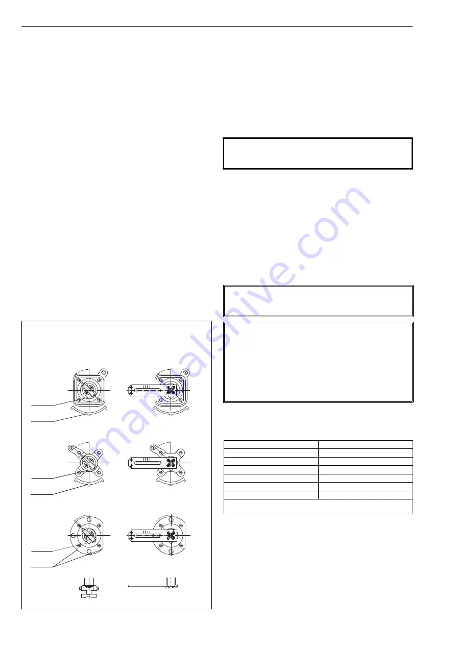
Fig. 4
Shaft coupling alternatives
45°
45°
45°
45°
45°
45°
ND9100
ND7100
ND9300
ND9200
ND7200
VDI/VDE 3845 mounting
Neles VC/VD actuators and
IEC 60534 mounting
pointer
pointer
pointer
marks on
housing
marks on
housing
marks on
housing
CAUTION:
Do not exceed the permitted supply pressure (8 bar /
115 psi) of the ND9000 and ND7000!
NOTE:
A valve controller mounted on a spring actuator must be
connected only as single-acting. See Fig. 7 and 8.
NOTE:
An excess of sealant may result in faulty operation of the
controller when accessed to pneumatic components.
Sealing tape is not recommended.
Ensure that the air piping is clean.
When pneumatic connector is removed, clean threads
carefully from dry sealant particles before mounting con-
nector back.
Table 3
Spring rates
Actuator type
Spring rate (bar/psi)
B1JK
3 / 43
B1J
4.2 / 61
B1JV
5.5 / 80
QPB
3 / 43
QPC
4.3 / 62
QPD
5.6 / 81
Adjust regulator pressure to a level that is max 1 bar (14.5 psi)
+ spring rate.


