10
Installation Guide
n
o
i
t
a
r
u
g
i
f
n
o
C
1
t
r
o
P
2
t
r
o
P
1
D
F
2
D
F
f
l
a
H
0
1
-
f
l
a
H
0
1
ll
u
F
0
1
-
f
l
a
H
0
1
P
U
f
l
a
H
0
0
1
-
ll
u
F
0
1
P
U
ll
u
F
0
0
1
-
ll
u
F
0
1
P
U
P
U
n
o
i
t
a
r
u
g
i
f
n
o
C
1
t
r
o
P
2
t
r
o
P
1
D
F
1
N
A
1
M
0
0
1
2
D
F
2
N
A
2
M
0
0
1
o
t
u
A
-
o
t
u
A
P
U
P
U
P
U
P
U
P
U
P
U
f
l
a
H
0
1
-
f
l
a
H
0
1
ll
u
F
0
1
-
f
l
a
H
0
1
P
U
f
l
a
H
0
0
1
-
f
l
a
H
0
1
P
U
ll
u
F
0
0
1
-
f
l
a
H
0
1
P
U
P
U
f
l
a
H
0
1
-
ll
u
F
0
1
P
U
ll
u
F
0
1
-
ll
u
F
0
1
P
U
P
U
f
l
a
H
0
0
1
-
ll
u
F
0
1
P
U
P
U
ll
u
F
0
0
1
-
ll
u
F
0
1
P
U
P
U
P
U
f
l
a
H
0
1
-
f
l
a
H
0
0
1
P
U
ll
u
F
0
1
-
f
l
a
H
0
0
1
P
U
P
U
f
l
a
H
0
0
1
-
f
l
a
H
0
0
1
P
U
P
U
ll
u
F
0
0
1
-
f
l
a
H
0
0
1
P
U
P
U
P
U
f
l
a
H
0
1
-
ll
u
F
0
0
1
P
U
P
U
ll
u
F
0
1
-
ll
u
F
0
0
1
P
U
P
U
P
U
f
l
a
H
0
0
1
-
ll
u
F
0
0
1
P
U
P
U
P
U
ll
u
F
0
0
1
-
ll
u
F
0
0
1
P
U
P
U
P
U
P
U
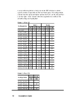
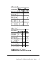
Use the following tables to help you set the DIP switches to obtain
specific modes of operation on the four board types. The configuration
column lists the speed and duplex options for Port 1 on the left and Port
2 on the right. “Auto” denotes that auto-negotiation is enabled. The
default settings are highlighted.
Table 1. TX to TX
Table 2. FL to FX


