14
Installation Guide
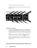
Insert the fiber optic connectors as shown below.
Once power is applied to the unit, verify correct connectivity via the
LK (link) LED.
RX
LK
TX
FX
M
M
II
x
PWR
100
FD
RX
LK
T
X
TX
10/100
RX
LK
TX
FX
M
M
II
x
PWR
100
FD
RX
LK
T
X
TX
10/100
RX
LK
TX
FX
M
M
II
x
PWR
100
FD
RX
LK
T
X
TX
10/100
RX
LK
TX
FX
M
M
II
x
PWR
100
FD
RX
LK
T
X
TX
10/100
II
x
PWR
100
FD
RX
RX
LK
LK
T
X
M
M
FL
TX
TX
10/100
II
x
II
x
PWR
100
FD
100
FD
RX
RX
LK
LK
T
X
T
X
TX
TX
10/100
RX
LK
TX
FX
M
M
II
x
PWR
100
FD
RX
LK
T
X
TX
10/100
RX
LK
TX
FX
M
M
II
x
PWR
100
FD
RX
LK
T
X
TX
10/100
FX
RX
LK
TX
M
M
II
x
PWR
100
FD
RX
LK
T
X
TX
10/100
MGT-10
LK
AT
C
O
N
S
O
L
E
1
PWR
A
B
R
ER
FX
PWR
RX
RX
LK
LK
M
M
FL
TX
TX
10/100
M
M
PWR
RX
RX
LK
LK
M
M
FL
TX
TX
10/100
FX
M
M
LK
AT
2
Twisted-Pair Connections
All models, excluding the R641-53, R641-55, R642-53 and R642-55,
provide one or two shielded RJ-45 connectors which support a maxi-
mum segment length of 100 meters. Use Category 3, 4 or 5 cables for
10Mbps segments; only use Category 5 cables for 100Mbps segments.
NOTE: Be sure to properly set the MDI-II to MDI-X
switch located
between the two port connectors. Refer back to
Step 2
if necessary.
Once power is applied to the line card, correct connectivity can be
verified via the LK (link) LED, if a device is connected to the remote
end of the cable.


