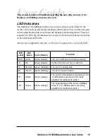
Radiance 10/100Mbps Interface Line Cards 7
DIP Switches
A set of six DIP switches, located on the back of the line card, allows
you to select from several modes of operation. These switches are
clearly marked on the printed circuit board.
*DIP switches also can be managed via console commands or with Metrobility’s NetBeacon® or WebBeacon
management software. Refer to the
Command Line Interface Reference Guide, NetBeacon Element Management
Software Installation & User’s Guide
or
WebBeacon Management Software Installation & User’s Guide
for software
management information.
II
x
PWR
100
FD
RX
RX
LK
LK
TX
TX
10/100
DIP
switches
Power Connector
Port 1
MDI-II to MDI-X Switch
Port 2
When setting DIP switches,
*
the UP position is when the lever of the
DIP switch is pushed away from the circuit board. The DOWN position
is when the lever is pushed toward the circuit board.
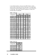
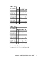
NOTE: Not all switches are available on every model. Unmarked
switches are reserved and should be left in the DOWN position. See the
table below for switch locations on the four board types.
d
r
a
o
B
e
p
y
T
n
o
i
t
i
s
o
P
h
c
t
i
w
S
P
I
D
)
t
h
g
i
r
o
t
t
f
e
l
(
1
2
3
4
5
6
X
T
-
X
T
1
D
F
1
N
A
1
M
0
0
1
2
D
F
2
N
A
2
M
0
0
1
X
T
-
L
F
1
D
F
1
R
L
L
F
C
L
L
2
D
F
2
N
A
2
M
0
0
1
X
F
-
L
F
1
D
F
1
R
L
L
F
C
L
L
2
D
F
2
R
L
L
—
X
F
-
X
T
1
D
F
1
N
A
1
M
0
0
1
2
D
F
2
R
L
L
F
C
L
L


