


www.metel.eu
5/10
Installation manual REV:201301
2G(200M)-2.1.4.E PoE++
LAN-RING System PoE++ Managed Switches
Installation and Setting
1. Mounting
Modification BOX – flat surface or DIN35
2. Connect supply
10-60VDC or 10-30VAC between terminals acc. to the
picture below. The supply is indicated by yellow LED PWR.
Overvoltage protections are grounded via GND terminal.
Connect GND terminal with ground using a cable of min.
1.5mm
2
diameter.
3. Connect optic fibers
terminated by SC connector (grinding PC). Optical output
is indicated by green LED of a given port. Blinking
indicates data.
It is necessary to connect optical ports cross-wise,
i.e. port P6 to port P7 etc.
Note: Before closing the optical ring one switch
must be configured as Master (menu "Ring").
4. Connect signal wires
RS485
– connect bus A+ and B-, A+ is positive In the idle
state.
USB
- connector for connection of USB A-B cable for local
management over SIMULand application.
RELAY -
in alarm state COM and N.O. are closed.
Alarm state is considered in the following situations:
supply failure, communication loss and optic fiber
interruption.
In non-alarm state COM and N.C. are closed.
IN, OUT -
digital inputs are activated by closing to GND or
by TTL level (0-0.3V „log 0“ and 2.7V-5V „log 1“).
TTL outputs can be mapped in switch management.
Revision:201301
Revision:201301 - Default
Main supply:
No PoE: 10...60VDC
10-30VAC
With PoE: 48...57VDC
With PoE+: 53...57VDC
Redundant supply
No PoE: 10...60VDC
With PoE: 48...57VDC
With PoE+: 53...57VDC
GND (PE)
GND (PE)
GND (PE)
+
+
~
~
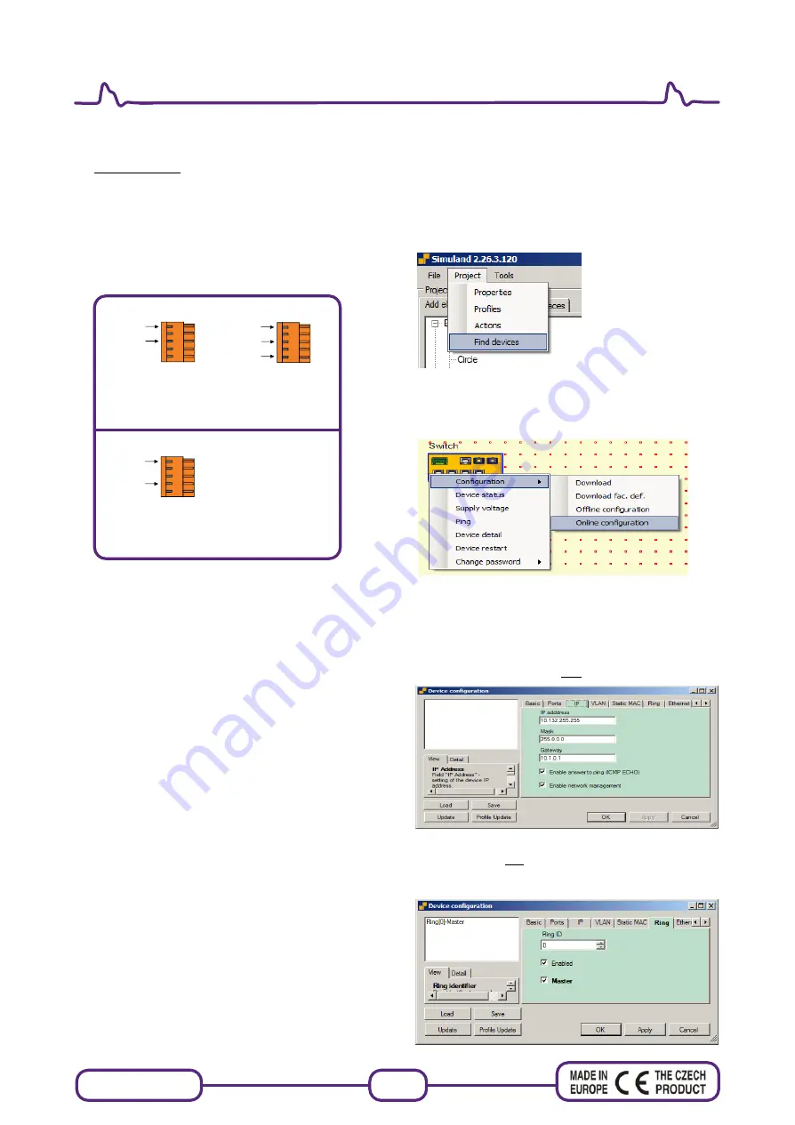
Fast configuration
1. Download and install
application SIMULand.
2. Run application SIMULand
3. From menu
„Project/Find devices“
scan avalaible
devices and put it on desktop. (IP adress network card
must be config in the same IP range as the IP address of
the switch)
4. Move the mouse cursor on the device, click on the left
and then the right mouse button. Select the menu
"Configuration / Online configuration"
and enter the
password.
5. Basic setting:
menu
„IP“
- setting the IP address, subnet mask and
gateway
„
Enable answer to ping
“ - enable / disable switch to reply
to a ping.
„
Enable network management
“ - unchecking the items
you will be able to switch only connect via USB.
6. Before closing the optical ring must be in the menu
„
Ring
“ always one switch is set to
„Master"
.
When use more optical ring you must set every optical
ring another „
Ring ID
“.


