


32
®
MIG150 - NLFRENES - v1.0 - 12112013
EN
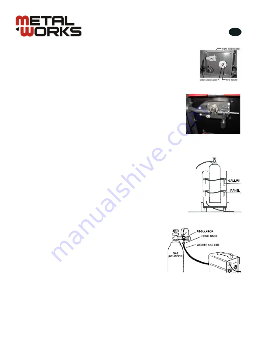
1. Open the right sideboard, and strip the wing nut from wire-feed spool axle.
2. Hold the spring and wire spool into wire-feed spool axle successively, and then hold
the wing nut (fig. 2).
3. Open the wire-feed impaction equipment, let the terminal of wire through
tube, wire-feed wheel, and import the tube of welding torch, then close the
equipment, adjust the impaction nut of wire-feed wheel (fig. 3).
4. Close the right sideboard.
- -
12
Step 2: Hold the spring and wire spool into wire-feed spool axle successively, and then hold the
wing nut (as diagram 2-3).
Diagram 2-3
Step 3: Open the wire-feed impaction equipment (C), let the terminal of wire through godet tube,
wire-feed wheel, and import the godet tube of welding torch, then close the equipment(c), adjust
the impaction nut of wire-feed wheel (as diagram 2-4).
Diagram 2-4
Step 4: Close the right sideboard
Chapter2 Assembly
2.3.3 Gas cylinder installation
The welder has a platform on the rear of the machine to support a gas cylinder. See diagram 2-5
for reference. If you plan on moving your welder about the shop, use only small cylinders (outside
diameter=140mm, 320mm
≤
height
≤
500mm, weight
≤
10Kg, service pressure
≤
20Mpa) for transport
safety. Large cylinders (outside diameter
>
140mm , or height
>
500mm, or weight
>
10Kg, service
pressure
≤
20Mpa) should be secured in a permanent location or to a separate cart, not to the welder.
Secure the small size cylinder with the gallus supplied with the welder. Small cylinders can be easily
secured in place using the top rack
“
A
”
.
Fig. 2
Fig. 3
Gas cylinder installation
The welder has a platform on the rear of the machine to support a gas cylinder
(fig.4). If you plan on moving your welder about the shop, use only small
cylinders (outside diameter = 140 mm, height ≤ 500 mm, weight ≤ 10Kg,
service pressure ≤ 20 MPa) for transport safety. Larger cylinders should be
secured in a permanent location or to a separate cart, not to the welder. Secure
the small size cylinder with the gallus supplied with the welder.
Connect the welder to the gas cylinder
Clean the threads of the gas cylinder valve. Also open the gas valve
for a few seconds to blow out any dirt of particulates which may
have gotten into the orifice in order to prevent them from entering the
regulator.
Check your regulator (outlet flow meter: 0-25 l/min,
inlet gauge: 0-25 MPa, pressure range for safe outpouring: 0 - 0.35
MPa) to make sure that it was supplied with a gasket.
Tighten the regulator coupling to the cylinder gas valve. Now connect
the welder gas line to the hose barb outlet on your regulator; a stainless
steel hose clamp can be used to insure a leak-proof connection.
(Fig. 5)
Check all connections for leaks by opening the regulator and cylinder
gas valves.
When the machine is not in use, always shut off the regulator and
cylinder gas valves.
- -
13
Diagram 2-5
2.3.4 Connection welder to gas cylinder
Clean the threads of the gas cylinder valve. Also open the gas valve for a few seconds to blow out
any dirt of particulates which may have gotten into the orifice in order to prevent them from entering
the regulator. Check your regulator (outlet flow meter: 0-25L/Min, inlet gauge: 0-25Mpa, pressure
range for safe outpouring: 0-0.35Mpa) to make sure that it was supplied with a gasket.
Tighten the regulator coupling to the cylinder gas valve. Now connect the welder gas line to the hose
barb outlet on your regulator; a stainless steel hose clamp can be used to insure a leak-proof
connection. (See diagram 2-6)
Check all connections for leaks by opening the regulator and cylinder gas valves.
When the machine is not in use, always shut off the regulator and cylinder gas valves.
Diagram 2-6
2.3.5Fixing the face shield (as diagram 2-7)
Fig. 4
Fig. 5
copyrighted
document
- all
rights
reserved
by
FBC


