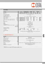
Metal Work REGTRONIC IO-Link Скачать руководство пользователя страница 24

24

7. TROUBLESHOOTING

ALARM
Supply voltage alarm too high
Supply voltage alarm too low
Alarm P. INP CORTOC. 0V
Alarm P. OUT CORTOC. 0V
P. INP alarm DISCONNECTED
P. OUT alarm DISCONNECTED
PRESSURE OUT OF RANGE ALARM


POSSIBLE CAUSES 

SOLUTION


Supply voltage higher 30 V 

Increase to a sufficient voltage.


Supply voltage below 18 V


Supply solenoid valve has shortcircuited 


Drain solenoid valve has shortcircuited 

Switch the unit off and back on again. If the


Fill solenoid valve disconnected 

alarm persists, contact the manufacturer.


Drain solenoid valve disconnected 


Downstream pressure exceeds 10200 mbar 

Check to see if the drain is blocked. The alarm resets   


automatically when the pressure drops below the 


threshold.

7.1 LIST OF ALLARMS

PROBLEM
The display does not come on

The unit does not respond or responds wrongly to the setpoint

The unit does not reach the desired pressure

The display shows an unreal value
The display is difficult to read
The unit adjusts continually

Other problems


POSSIBLE CAUSES 

SOLUTION


No power supply IO-Link 

Check the power supply, make sure it is


enough and check the wiring is in accordance


with the wiring diagram


Wrong input signal configuration 

Configure the appropriate type of input from the menu


Check the signal wire is connected to the right 


pin


Setpoint too low 

Provide a suitable setpoint


The full-scale setting is at a lower pressure 

Set the full scale correctly 


than desired


The supply pressure is too low 

Increase the supply pressure


Wrong unit of measurement 

Check the unit of measurement


Poor contrast 

Adjust the contrast


Air leak in the circuit after the unit 

Eliminate the leak


Continuous variation in volume  

Normal behaviour; the unit has to keep


adjusting the maintain the preset pressure


Deadband too small 

Increase the deadband


Contact the manufacturer

Содержание REGTRONIC IO-Link

Страница 1: ...REGTRONIC IO Link MANUALE D USO REGTRONIC IO Link USER MANUAL...

Страница 2: ...Onde evitare movimenti incontrollati o danni funzionali prima di iniziare qualsiasi intervento di installazione o manutenzione scollegare alimentazione dell aria compressa alimentazione elettrica dell...

Страница 3: ...o disinserire il connettore pericolo di danni funzionali 3 MESSA IN SERVIZIO 3 1 CONNESSIONI A REGTRONIC IO Link Collegare il connettore M12 al Master IO Link 3 2 INSTALLAZIONE DI REGTRONIC IO Link I...

Страница 4: ...ere OK Selezionare l Unita di Misura desiderata utilizzando i tasti freccia premere OK N B Le impostazioni di pressione set pressione banda morta fondo scala e minima pressione se impostate dal Master...

Страница 5: ...ccia premere OK 4 2 3 FONDO SCALA Indica la Pressione massima regolata Il comando analogico viene ripartito sul Fondo Scala Il segnale di out analogico indica la pressione regolata ed 0 10 VDC per 0 1...

Страница 6: ...elettrovalvole Selezionare DEBUG premere OK Selezionare PIN premere OK l elettrovalvola di carico si attiva la pressione aumenta Premere OK l elettrovalvola di carico si disattiva la pressione si stab...

Страница 7: ...tazione dei parametri premere contemporaneamente i tasti OK ed ESC Per scorrere il men e modificare i parametri utilizzare i tasti freccia su freccia gi N B REGOLATORE algoritmo di regolazione ottimiz...

Страница 8: ...FACCIA 6 DIAGNOSTICA LED PRESSURE SIGNIFICATO lampeggiante In regolazione ON Regolazione OFF OFF Manca la tensione di alimentazione IO Link LED IO Link SIGNIFICATO ON Stato operativo lampeggiante Stat...

Страница 9: ...non raggiunge la pressione desiderata Il display mostra un valore irreale Il display poco leggibile L unit regola di continuo Eventuali altri problemi POSSIBILE CAUSA SOLUZIONE Manca la tensione di a...

Страница 10: ...logo Selezionare il file 02282REGTRONIC e installarlo nella porta designata Configurazione dei Parametri dell unit Oltre ai parametri configurabili tramite display sono disponibili due parametri aggiu...

Страница 11: ...2C 50 mbar Fondo Scala 68 0 UINT 16 bit 100 10000 mbar 00 64 27 10 10000 mbar Minima Pressione 67 0 UINT 16 bit 0 50 FS 00 00 13 88 0 mbar Velocit di regolazione 74 0 UINT 8 bit 0 10 00 0A 10 Tipo di...

Страница 12: ..._2byte Dopo aver caricato il progetto nel Controller collegare Regtronic alla rispettiva porta IO Link Configurazione dei Parametri dell unit La configurazione dei parametri dell unit pu essere effet...

Страница 13: ...e bar Pressione di regolazione 1 bar Pressione MAX di alimentazione bar 11 Temperatura di esercizio C 0 50 Campo di regolazione della pressione bar 0 05 10 minima pressione e fondo scala impostabili P...

Страница 14: ...po totale di attivazione dell elettro pilota attivazione di una segnalazione di superamento del 60 della vita media contatore Allarmi Corto Circuito contatore Allarmi Circuito Aperto I dati in formato...

Страница 15: ...15 NOTE Esempio di visualizzazione in Siemens S7 PCT...

Страница 16: ...16 NOTES...

Страница 17: ...nk diagnostics Graphical display and keypad to display the pressure unit of measurement and parameter setting Before carrying out any installation or maintenance work switch off the following compress...

Страница 18: ...unplugging the connector risk of functional damage 3 COMMISSIONING 3 1 CONNECTIONS TO THE IO Link REGTRONIC Connect the M12 connector to the IO Link master module 3 2 INSTALLING THE IO Link REGTRONIC...

Страница 19: ...Select the desired unit of measurement using the arrow keys then press OK N B Pressure settings like pressure regulated dead band full scale and minimum pressure when set by the Master IO Link are al...

Страница 20: ...his indicates the maximum preset pressure The analog command is divided over the Full Scale The analog output signal indicates that the preset pressure is 0 10 VDC for 0 10 bar Examples with maximum p...

Страница 21: ...s Select DEBUG and press OK Select PIN and press OK The in solenoid valve activates and the pressure increases Press OK The in solenoid valve deactivates and pressure stabilizes Select POUT and press...

Страница 22: ...her to access the parameter setting menu Use the up and down arrows to scroll through the menu and modify the parameters N B REGULATOR regulation algorithm optimized for the type of regulator 0 Regtro...

Страница 23: ...ate of the COM 7 LED INTERFACE 6 DIAGNOSTICS LED PRESSURE SOLUTION Flashing In regulation ON Regulation OFF OFF No IO Link power supply LED IO Link SOLUTION ON Operating state Flashing Pre operating s...

Страница 24: ...s wrongly to the setpoint The unit does not reach the desired pressure The display shows an unreal value The display is difficult to read The unit adjusts continually Other problems POSSIBLE CAUSES SO...

Страница 25: ...to the catalogue Select the 02282REGTRONIC file and install it in the designated port Configuration of unit parameters In addition to the display configurable parameters two more parameters are availa...

Страница 26: ...ar Full Scale 68 0 UINT 16 bit 100 10000 mbar 00 64 27 10 10000 mbar Minimum Pressure 67 0 UINT 16 bit 0 50 FS 00 00 13 88 0 mbar Regulation speed 74 0 UINT 8 bit 0 10 00 0A 10 Type of regulator 71 0...

Страница 27: ...d 2 byte Output I O_2 _2byte First load the Controller project and connect the Regtronic to the associated IO Link port Parameter Configuration The parameters of the unit can be configured by accessin...

Страница 28: ...sure 1 bar MAX inlet pressure bar 11 Temperature range C from 0 to 50 Pressure regulation range bar from 0 05 to 10 settable full scale and minimum pressure Flow rate at 6 3 bar P 0 5 Nl min 10 1300 1...

Страница 29: ...time counter activation of a report indicating operating cycle exceeding 60 Short Circuiting Alarm counter Circuit Open Alarm counter Data in hexadecimal format is available as system variables using...

Страница 30: ...30 NOTES Example of display in Siemens S7 PCT...

Страница 31: ...31 NOTES...

Страница 32: ...32 www metalwork eu M0030212 IT_EN IM00_01 2020 NOTES...

Отзывы: