


17
IO-Link Regtronic is an electronic pressure regulator complying with IO-Link communication standard. It offers advanced diagnostic functions and can
be linked to an IO-Link Master module.
It supports COM3 communication, according to V1.1 specification and Class A Port connection.
INTENDED USE
WARNING
The Regtronic IO-Link must only be used as follows:
• as designated in industrial applications;
• in systems fully assembled and in perfect working order;
• in compliance with the maximum values specified for electrical ratings, pressures and temperatures.
• Only use power supply complying with IEC 742/EN60742/VDE0551 with at least 4kV insulation resistance (PELV).
This manual is intended exclusively for technicians qualified in control and automation technology, who have acquired experience in installing,
commissioning, programming and diagnosing programmable logic controllers (PLC) and Fieldbus systems.
TARGET GROUP
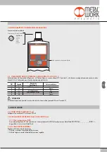
1. FEATURES
• Electrical connection: M12 5-pin connector.
• Preset pressure range 0.05-10 bar with possible full scale and minimum pressure regulation.
• 10-300 mbar adjustable deadband.
• Supply pressure: FS+ at least 1 bar, max 11 bar.
• 24 VDC power supply.
• IP65 index of protection.
• LED indicating pressure achieved and IO-Link diagnostics.
• Graphical display and keypad to display the pressure, unit of measurement and parameter setting.
Before carrying out any installation or maintenance work, switch off the following:
• compressed air supply;
• the operating power supply to control electronics.
2.1 PNEUMATIC CONNECTION
Pneumatic connection is via the threaded holes in the body.
It is important for the regulator pressure not to exceed 11 bar and the compressed air to be filtered at 10 μm and dried, to prevent impurities or
excessive condensate from causing a malfunction.
The supply pressure must always be higher than the preset pressure.
The regulator pressure must be at least 1 bar higher than the full scale value.
If a silencer is mounted on the outlet, the flow rates and response times may vary. Check the silencer periodically for clogging and replace if necessary.
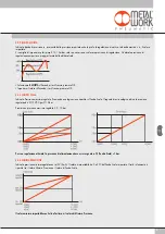
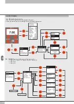
2.2 OPERATING PRINCIPLE
Using a software algorythm, the control circuit compares the input signal with the output pressure measured by the pressure sensor.
When there is a change, it activates the inlet and outlet solenoid valves to re-establish an equilibrium.
This gives an output pressure that is proportional to the input signal.
N.B.: removing the power supply, the outlet pressure doesn’t get discharged.
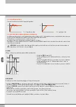
2.2.1 FUNCTION DIAGRAM
2. INSTALLATION / OPERATION
P
DISPLAY
CONTROL
CIRCUIT
INLET SOLENOID
VALVE
FEED
INPUT SIGNAL
OUTPUT SIGNAL
OUTLET SOLENOID
VALVE
PRESSURE SENSOR
IN
OUT
Содержание REGTRONIC IO-Link
Страница 1: ...REGTRONIC IO Link MANUALE D USO REGTRONIC IO Link USER MANUAL...
Страница 15: ...15 NOTE Esempio di visualizzazione in Siemens S7 PCT...
Страница 16: ...16 NOTES...
Страница 30: ...30 NOTES Example of display in Siemens S7 PCT...
Страница 31: ...31 NOTES...
Страница 32: ...32 www metalwork eu M0030212 IT_EN IM00_01 2020 NOTES...


