background image

28

2. Metal Loss

The metal loss value is available both through the “MEASURE PROBE” and “VIEW STORED DATA”
functions, and is shown as MILS (1 MIL = 0.001 inches). The instrument automatically performs the
calculation shown in equation 1, p. 27, and displays the result on the MS3500E/3510E screen.

The metal loss value shown is the total metal loss since the probe was new. Consequently, this
value is only valid when the probe used is initially installed as new. 
If a partially consumed probe
is attached to an MS3500E/3510E to perform a logging sequence, the MILS value shown will be an
overestimation of metal loss at the present locations by an amount equivalent to the thickness loss prior
to the commencement of logging operations.

3. Corrosion Rate

This value is also available through the “MEASURE PROBE” and “VIEW STORED DATA” functions
and is expressed as MPY (1 MPY = 0.001 inches per year). This value is calculated on the basis of
equation 2, p.27.
Again, the calculation is an average corrosion rate assuming an as new condition for the probe
element at the beginning of the logging sequence.

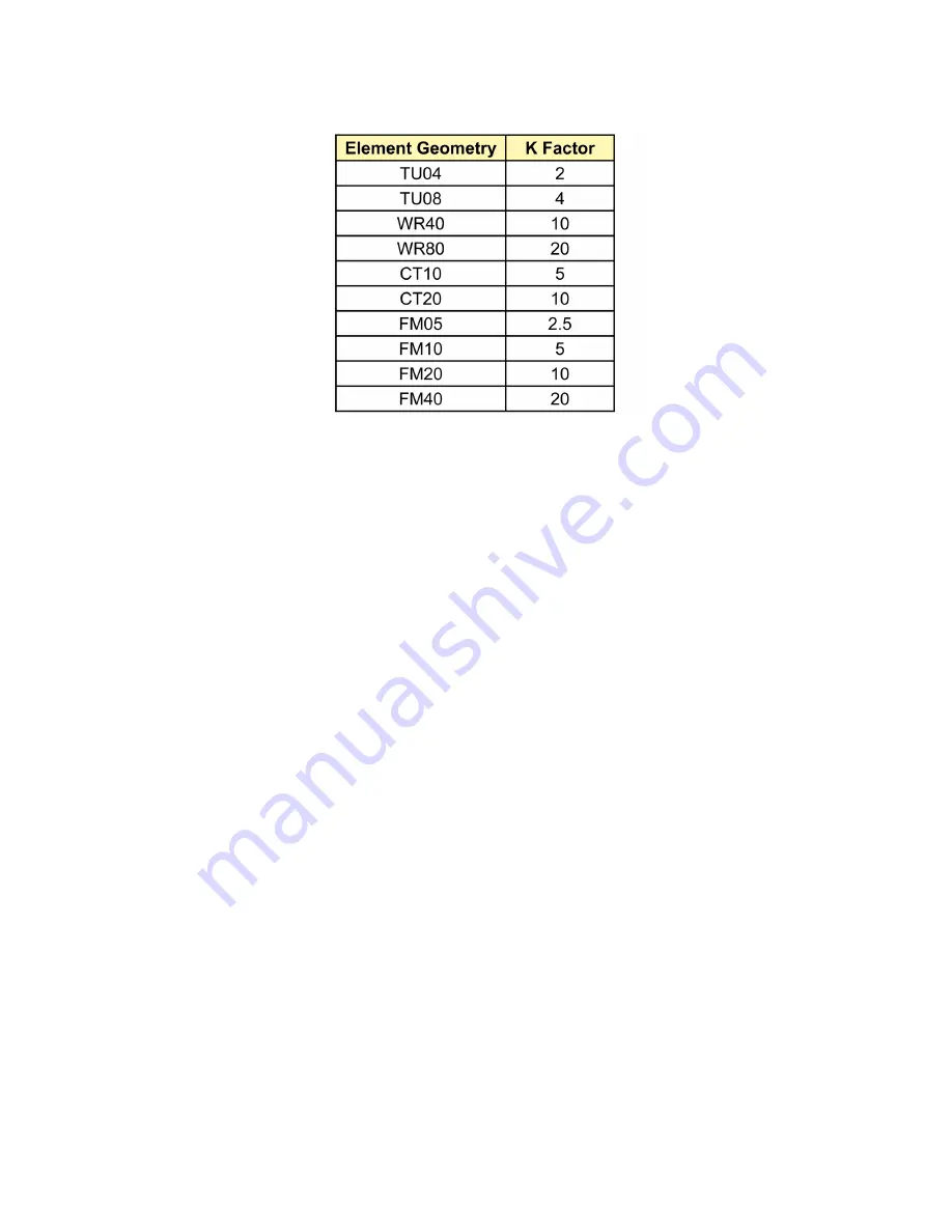
Table 1.  Probe Constant

Содержание MS3500E

Страница 1: ...E Remote ER Data Logger MetalSamplesCompany A Division of Alabama Specialty Products Inc 152 Metal Samples Rd Munford AL 36268 Phone 256 358 4202 Fax 256 358 4515 E mail msc alspi com Internet www metalsamples com ...

Страница 2: ... ...

Страница 3: ...ction s 7 III Setup and Operation 8 A Main Menu Overview 8 B Program Setup 10 1 Set Time and Date 10 2 Enter Probe ID 11 3 Start Data Logging 12 C Measure Probe Function 13 D View Stored Data Functions 14 E SetReadingIntervalFunction 15 F Downloading Data 16 1 Upload to PC 16 2 Upload to MS1500E 25 G SystemShutdownFunction 26 H Test Mode Function 26 I Data Interpretation 27 1 Probe Reading 27 2 Me...

Страница 4: ... D ER Probe Body Design 38 AppendixA MS3500E Specifications 41 Appendix B Testing the MS3500E MS3510E with the ER Meter Prover 42 Appendix C MS1500E Select Probe ID 44 AppendixD ReturninganInstrumentforRepair 47 Appendix E Warranty 49 Appendix F Installation Drawing of MS3500E in Hazardous Location 50 ...

Страница 5: ...ed reviewed or re ported by conventional spreadsheet database or mathematical software packages TheinfraredcommunicationlinkisanintegralpartoftheintrinsicallysafedesignoftheMS3500E 3510E Opticalinsteadofelectrical thisuniquefeaturepermitsdatadownloadingwithoutremovingthe instrumentor memorymodule fromthehazardousarea AnotheruniquefeatureoftheMS3500E 3510Eisthehighlevelofonboardintelligence Thetwo ...

Страница 6: ...ector MS3510E Only IN3500 2 1 OptilinkCable IN3500 4 1 10 Ft Probe Cable IN3500 5 1 Meter Prover IN3500 6 1 Serial Port Adapter IN3500 7 1 OperationsManual Upon receipt of the instrument the user should verify that the above listed accessories are included Anyshortageshouldbereportedimmediatelyto Metal Samples Phone 256 358 4202 Fax 256 358 4515 E mail msc alspi com ...

Страница 7: ... to NEMA 4X IP 66 weatherproof standards makingitsuitableforthemostrigorousofoutdoorenvironments The overall dimensions of the unit are 12 1 4 height 9 width 4 3 8 depth making it a conve nientsizetomounteveninthemostconfinedoflocations Forthebestresults theinstrumentshouldbe mountedwithintenfeetoftheprobelocation Tofacilitatethis theunithasaversatilemountingflange withfour 31 diameter mountinghol...

Страница 8: ...ery 12 or 24 hours will yield a battery life in excess of twelve months Generally to avoid unexpected power drains batteries should be replaced once every six months In the instance of a low reading interval 1 per 4 hours or less three monthly battery replacements is advisable Batteries are mounted in the back of the MS3500E MS3510E behind the instrument screen and keyboard panel The batteries are...

Страница 9: ...ouldbeconnectedtothe A terminalof the ET0612 mating connector and the negative lead to the B The loop can then be connected to the 4 20mAinstrumentoutlet Figure 3 MS3510E Current LoopTermination The loop should be powered by 10 24 VDC For hazardous applications an appropriate Zener barrier should be installed in the loop or power should be supplied from an intrinsically safe repeater power supply ...

Страница 10: ...gralconnectorswithaguidingkeywaytoensurecorrectpinalignmentwhen attached The female connector MS3106E145 6S mates with the probe or HA700110 5 probe adaptor and the male connector mates with the central terminal on the base of the MS3500E 3510E unit The length of the extension cable has been carefully determined so as to avoid excessive signal noise Longer extension cables should only be employed ...

Страница 11: ...ely at major electronics retailers To download data from the MS3500E to a MS1500E connect the Optilink Cable directly to the MS1500E Detailedinstructionsofdatadownloadingaregivenonp 16 UPLOAD TO PC SAFE AREA ONLY UPLOAD TO MS1500 MS1500 HANDHELD DATA LOGGER OPTI LINK CABLE MS3500 MS3510 DATA LOGGER Ò US S I L E T D REMOTE ER DATA LOGGER TRANSMITTER MS3510E MS3500 SERIAL PORT ADAPTER SERIAL TO USB ...

Страница 12: ...rstofthefunctionscreens thatconstitutesthemainmenu AseriesofninefunctionscreenscanbeaccessedsimplybyscrollingusingKEY1ontheinstrument keypad Each of the nine function screens allows entry into a submenu to initiate an action such as MEASURE PROBE or STARTDATALOGGING alternatively it allows input of data such as probe identificationorreadinginterval Eachofthefunctionscreensandtheirsubmenusarefullye...

Страница 13: ...art updata SETREADINGINTERVAL Thisallowstheinitialreadingintervalthatisinputunder PROBE ID to be changed without deleting stored data SETMEASUREMENTTIME Thisallowstheinitialmeasurement polarization timethatis input under PROBE ID to be changed without deleting stored data SETTIMEAND DATE This constitutes the initial step of start up data allowing correct settingofthe realtime clock UPLOAD TO MS150...

Страница 14: ...formation Either key will automatically return the user to the MEA SUREPROBE screenofthemainmenu Ifthetimeanddatehasbeenrejected scrolltothe SETTIME DATE function screen reenter the submenu and make the necessary corrections If the time and date are correct and the user has used KEY 2 to accept the information scroll to the ENTER PROBE ID functionscreentocontinuewithprogramsetup Please note that t...

Страница 15: ...geometry and thickness KEY 1 allows the user to scroll through the element identifications and KEY 2 will enter the appropriate element ID once it is located It should be noted that the variety of element geometries and thicknesses that is offered by the various probe manufacturers tends to increase Consequently it is possible from time to time that the user may encounter a probe element style tha...

Страница 16: ...highest frequency 1 per hour downloading can be scheduled at intervals as great as 129 without data corruption by overwriting now required to access the PROBE ID function and reset correct the probe ID the element ID and thereadingfrequencypriortocommencingwiththedataloggingprocess Upon entry of the probe element ID the screen will automatically change to the data collection rate screen This allow...

Страница 17: ...PLEASEWAIT notation After approximately 30 seconds thereadingwillbecompleteandthethirdsubmenuscreenwillbeautomaticallydisplayed This screen will show the current probe reading as an integer between 0 1000 and will give a KEY 1 EXIT option and a KEY 2 ENTER save option KEY 1 will return the user to the MEASURE PROBE functionscreen KEY2willsavetheprobereadingandautomaticallydisplaythefourthsubmenu s...

Страница 18: ...g in probeunits Thereadingnumberismerelythetotalnumberofreadingsstoredupto andincluding the reading displayed The probe unit reading is an integer from 0 to 1000 that indicates the percentage of effectiveprobethicknessconsumed PreviousreadingsmaybeaccessedsequentiallyusingKEY2 KEY l will exit the review screen and display metal loss MILS and average corrosion rate MPY for thereadingnumberdisplayed...

Страница 19: ...creen KEY2thenallowsentryintothesubmenu Thecurrentreadingintervalisdisplayedasdaysandhours IndividualdigitsmaybealteredusingKEY 1 andenteredusingKEY2 Afterthefinalhourdigitisentered thescreenwillautomaticallychangeto areadingintervalconfirmationscreen Theintervalasenteredisdisplayed KEY1willexittothe MEASUREPROBE mainfunctionscreenwithoutentering saving thenewinterval KEY2willenter save thenewread...

Страница 20: ... MS3500E 3510E units for subsequent transfer to a PC 1 Upload to PC To transfer data to a PC it is necessary to install the Corrosion Data Management Software To run the Corrosion Data Management Software you need a PC that meets the following requirements Pentium class processor Windows 95orhigheroperatingsystem 16 MB of RAM 10 MB of available hard disk space VGA monitor with 800 600 or greater r...

Страница 21: ... installation is complete you should remove the setup disk then reboot your computer Instrument Download Center The Instrument Download Center is a simple tool for retrieving data from Metal Samples ER and LPR dataloggerinstruments Todownloaddatafromaninstrument Connect the instrument to an available PC serial port or USB port see page 7 Turn the MS3500E on Run the Corrosion Data Management Softwa...

Страница 22: ...ect the port to which the instrument is connected If the COM port number is unknown it can be found inWindows Device Manager under Ports COM LPT Selecting an Instrument Use the Instrument option box to select the model of Metal Samples instrument being downloaded This sets the appropriate communication parameters which will be displayed in the status bar at the bottom of the window 9600 N 8 1 for ...

Страница 23: ...dow click the Chart Data button If the data has not yet been saved the user will be prompted to do so before the charting process begins For more information on charting data see the DataAnalysis section DataAnalysis TheDataAnalysisutilityisaconvenienttoolforchartingdatafromMetalSamplesERandLPRdata logger instruments The DataAnalysis utility can be opened from the Main Menu or it can be opened dir...

Страница 24: ... review By default all data points will be included in the chart However data points can be turned off or ex cluded from the chart If the Excluded flag appears in the status column for a data point that data point will not appear in the chart To toggle the exclude include status of a data point double click the data point or select the data point and click Exclude Include in the Options menu Print...

Страница 25: ... the File menu This will copy both the chart and the raw data to the Windows Clipboard The chart can then be inserted into otherapplicationsusingthePastefunction Note Insomeapplications usingthePastefunctionwill insert the raw data instead of the chart In this case use the Paste Special function then select Picture to insert the chart Chart Tools Statistical Data The Statistical Data tab at the bo...

Страница 26: ...ear immediately after clicking the data point hold the mouse pointer stationary over the chart background for a moment The Tools Menu TheToolsmenucontainsacollectionofutilitiesforviewingandmanipulatingthechart TheTools menu can be accessed by clicking Tools on the menu bar or by right clicking anywhere on the chart o Data Markers Show Data Markers toggles the data markers on and off o Mean Value S...

Страница 27: ...t type can be set to Line Chart Bar Chart or Area Chart by selecting the appropriate button in the Chart Type box The default chart type is Line Chart o Data Series Color Data Series Color displays a color selection box which allows the user to select the brush color for the plot line The default color for the plot line is Blue o ZoomIn Zoom In allows a region of the chart to be enlarged so that i...

Страница 28: ... rate to be calculated between any two data points on the chart To calculate the corrosion rate click Calculate Corrosion Rate then click two data points The corrosion rate between those two data points will be displayed In calculate mode the mouse pointer will change to an arrow question mark When calculate mode ends the mouse pointer will return to its normal state To cancel a calculation click ...

Страница 29: ...cationsmodeshouldbeselectedontheMS3500E 3510Einstrument Thisisachievedby scrollingthroughthemainfunctionsmenu usingKEY1 untilthe UPLOADTOMS1500E screenis reached The submenu is accessed using KEY 2 The MS3500E 3510E screen will now display WAITING FOR LINK UP and a KEY1 exit option The MS3500E 3510E is now waiting for the downloadinstructionfromtheMS1500E Thisinstructionisgivenbypressingenteronthe...

Страница 30: ...reen will now ask for confirmation KEY 2 will activate system shutdown KEY 1 will return the user to the main function screens If KEY 2 is used to activate SYSTEMSHUTDOWN dataloggingwillceasebutallexistingdatawillberetainedinmemory When the user wishes to reactivate the logging process either key can be used to access the screen andKEY1willthenresumetheloggingprocess H Test Mode Function Thetestmo...

Страница 31: ... between 0 1000 and represents the percent age of the effective probe element thickness consumed since the probe was inserted into the corrosive system This value is most commonly used to calculate metal loss and or corrosion rate as shown below ML 1 CR 2 ML METAL LOSS IN MILS X INSTRUMENT READING AT ANY GIVEN TIME X2 INSTRUMENT READING AT TIME t2 X1 INSTRUMENT READING AT TIME t1 T TIME LAPSE DAYS...

Страница 32: ...d as new If a partially consumed probe is attached to an MS3500E 3510E to perform a logging sequence the MILS value shown will be an overestimationofmetallossatthepresentlocationsbyanamountequivalenttothethicknesslossprior tothecommencementofloggingoperations 3 Corrosion Rate Thisvalueisalsoavailablethroughthe MEASUREPROBE and VIEWSTOREDDATA functions and is expressed as MPY 1 MPY 0 001 inches per...

Страница 33: ... life units PLU at the receiving devicebyapplyingthefollowingsimplealgorithm PLU 3 A Loop Current in mA Total metal loss ML may be derived from ML 4 A Loop Current in mA K Probe Constant Corrosion rate CR may also be derived as CR 5 A 4 1000 16 A 4 K 16 A2 A1 K x 365 16 T2 T1 A2 Loop Current at Time T2 A1 Loop Current at Time T1 T2 End Time Days T1 Start Time Days K Probe Constant ...

Страница 34: ...istancemeasurementsofametal alloyelementthatiscontinuouslyexposedto acorrosiveenvironment willprovidedataontherateandextentofcorrosionforthatalloy environment combination In practice resistance is also a function of temperature Therefore electrical resistance corrosion probes need some means to compensate for the spurious effects of temperature change This is achieved by constructing the probes wi...

Страница 35: ...tion only of the loss in metal thickness on the exposed element and therefore of corrosion Thisresistanceratio RExp RRef ismeasuredeitherperiodicallywithaportableinstrument orcontinu ouslywithavarietyofcontinuous automaticrecording datalogginginstrumentsandreadaspercentage thicknessloss Thus totalmetallossversustimeisdirectlyavailable andcorrosionrateisindirectly availableastheslopeofthelineformet...

Страница 36: ...msexhibitingmoderatecorrosionrates 5 20mpy Cylindricalelementsaremadefromhollowcylindersandareextremelyrobust Theyarewidelyusedin hightemperaturesandhighflowrateconditions Theytendtobesensitivetonoiseandsomewhat sluggishinresponse Consequently theyareonlyrecommendedformoderatetohighcorrosionrates 20 50 mpy Flush elements are designed to be located flush with the corroding surface of the vessel pip...

Страница 37: ...ementdesigns Table 2 Element Temperature and Pressure Ratings Note Thetemperatureandpressurelimitationsgivenabovemaybesubjecttomodificationaccordingto theprobebodydesign Thisisdiscussedlaterinthismanual Afinalissuewithrespecttosensingelementsismaterialofconstruction Generally thisshouldbe selectedtomostnearlymatchthatoftheplantorequipmentunderconsideration Almostanygeometric configurationandthickn...

Страница 38: ...ollowingfunctions 7 8 ML METALLOSSINMILS X INSTRUMENTREADINGATANYGIVENTIME X2 INSTRUMENTREADINGATTIME t2 X1 INSTRUMENTREADINGATTIME t1 t TIMELAPSE DAYS BETWEENREADINGSX1 ANDX2 CR CORROSIONRATEINMILSPERYEAR K PROBECONSTANT The probe constant K is a function of the element thickness and geometry Table 3 lists the K factors forvariouscommonelements ML X x K 1000 X2 X1 x K x 365 1000 t CR ...

Страница 39: ...me whichisthetime requiredtoobtainasignificantreadingchangeatagivencorrosionrate isinverselyproportionalto elementthickness Thus theusermustmakesomecompromisebetweenlifeandresponsetimewhen selectingasensingelement Figures8and9provideageneralguideforselectingoptimumlifeand responsetimecombinations Theothermajorperformancecharacteristicrelatedtoelementgeometryismeasurementreproducibility Underidealc...

Страница 40: ...36 Figure 8 Element Selection Guide Element Life ...

Страница 41: ...37 Figure 9 Element selection guide response time ...

Страница 42: ...mprises a welded flange or NPT pipe plug entry on a cylindrical shaft Theprobeisavailableinavarietyofinsertionlengths althoughnolengthadjustmentisavailable hence thename fixed length probe Thisprobeisavailableinallelementstyles butforpipeplugentry theflushelementvarietiescanonly be accommodated on bushing sizes of 1 NPTor greater Pressure and temperature ratings are 3000 PSI and 500 F for pipe plu...

Страница 43: ...nserted into the system through a customer supplied ball valve and can be inserted or removed from pressurized systems without shutdown Retractable probes can be operated at pressures to 1500 psi and 500 F Metal Samples EasyTool is recommended for probe insertion or retraction in systems with pressure over 150 pounds Allelementconfigurationsareavailableforretractableprobesandmostcanbeaccommodatedt...

Страница 44: ...Figure 12 The retrievable probe which is normally constructed in AISI 316L stainless steel can be inserted and removed from systems operating up to 3600 psi without system shutdown This is achieved by using a portable valve and retrieval tool that can be moved from probe location to probe location as insertion or removalisrequired Figure 12 Retrievable ER Probe Cover HP Hollow Plug Assembly HP Acc...

Страница 45: ...d ER probe type Wire Loop Tube Loop Cylindrical Flush Strip etc Range 0 1000 digits representing 0 100 of probe life Resolution 1digit CycleTime 1 Hour to 99 Days Electrical Data PowerRequirements Six 1 5V AA Batteries Max Probe Cable Distance 10 ft 3 05 m OutputSpecifications RS 232 Output in Comma DelimitedASCIIText Format 4 20mA Current Loop Output MS3510E Only Class I Division 1Groups A B C an...

Страница 46: ...atthetime If the instrument measures close to the printed value on the Meter Prover label thentheinstrumentandcablearebothworkingproperlyandnofurthertesting is required If there is a significant difference in the measured value or if you getanerror continuetestingasfollows 4 Disconnect the ER Meter Prover from the probe cable 5 Disconnecttheprobecablefromtheinstrument 6 Connect the ER Meter Prover...

Страница 47: ...the listed value as explained in step 3 above It is also important to note that each ER Meter Prover is serialized to match the instrument it is shipped with and its measured value may differ if it is used with another meter If it is necessary to use an ER Meter Prover with another meter it is recommended that you establish a baseline value for the ER Meter Prover with the other meter ...

Страница 48: ...ings enterintomemorytheidentificationofanewprobe deletefrommemorytheidentificationofaprobe To run any of these three options choose SELECTPROBE ID from the Main Menu The next screen allows you to choose the functions to ENTER or DELETE a probe ID or to select a probe ID from thosealreadyinmemoryforwhichyouwishtomakemeasurements Whentransferringdatafroman MS3500E unit the user will invariably selec...

Страница 49: ... one by pressing the arrow keys See p 28 for a list of probe types supported by the MS1500E 1 Press the arrow key to select a probe ID 2 Press ENTER To enter the ID of a new probe select ENTER NEWPROBE the next screen allows you to enter the ID number and the type 1 Enter the probe ID use the number keys press the DOWN arrow if you make an error 2 Press the UParrow when you ve entered the correct ...

Страница 50: ... probe when you replace one Note that when you delete a probe you also delete all the readings for that probe You might want to transfer the readings to a computer before deleting them by using the COMMUNI CATIONS option in the Main Menu see COMMUNICATIONS in the MS1500E manual It is occasionally necessary to remove the ID of a probe from memory for example whenthememorybankisfull when a probe is ...

Страница 51: ...lable packtheinstrumentinarigidcardboardorwoodcarton Surroundtheinstrumentwithaminimum of three inches of resilient packing material such as foam rubber or shredded newspaper 2 Shiptheinstrumentprepaidviaairfreightorairexpressto Metal Samples 152 Metal Samples Rd Munford AL 36268 3 Contact Metal Samples by telephone 256 358 4202 or fax 256 358 4515 and tell them a thenameoftheairlinecarryingtheins...

Страница 52: ..._____ Company s Purchase Order for Original Sale_________________________ 3 ReturntheInstrumentto Company Name ________________________________________________ _____________________________________________________________ Address Location ______________________________________________ ____________________________________________________________ Telephone Number ____________________________________...

Страница 53: ...ation as to the existence and cause of the defect TheforegoingshallconstitutethesoleandexclusiveremedyofanypurchaserofMetalSamples products for breach of warranty and is exclusive and in lieu of all other warranties expressed implied orstatutory includingtheimpliedwarrantiesormerchantabilityandfitness InnoeventshallMetal Samples be liable for special or consequential damages or for any delay in th...

Страница 54: ...Installation Drawing of MS3500E in Hazardous Location 152 Metal Samples Rd Munford AL 36268 Phone 256 358 4202 Fax 256 358 4515 ALABAMA SPECIALTY PRODUCTS INC ...

Отзывы: