background image

MicroVol-1100 User manual 1.6


Operation


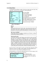
3.3.1 Status Screen 

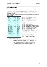
The Status Screen displays current MicroVol status information. The data can not be 
changed from this screen. Sample volume and Corrected sample volume data is 
updated every minute, all other data updates instantly. Corrected sample volume is 
used to calculate particulate concentration and has been corrected to standard 
Reference conditions. 
Note: All YES/NO conditions must be met before sampling takes place in Automatic 
sampling mode. 


Displays current volumetric flow-rate 


Displays sample volume 


Displays current ambient temperature 


Displays current barometric pressure 


Displays current wind speed 


Displays current wind direction* 


Displays Relative Humidityl 


Displays sample volume corrected to STP** 


Displays sampling duration (pump running) 


Displays current power supply voltage 


Displays pump load (0.000-2.000) 


Displays current day of the week 


Is current time/date combination active? 


Is current date after timer start date? 


Is current date before timer end date? 


Is this an active sampling day? 


Is wind condition (sector/speed) active? 


Is power supply voltage in range? 


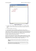
Figure 11 Status Screen


* - if no sensor is installed, wind direction displays random data 
** - Standard Temperature and Pressure, set in the Setup menu. 


Note

: Some parameters may be reset to zero by Clearing 

Accumulated data in the Setup 

 Logger Setup Menu. 

Flow l/min 

3.000 

Tot. Vol. 

l  708.02 

Temp. C 

22.90 

Press. mmHg 

763.4 

Wind Sp.  

m/s  12.980 

Wind Dir. 

deg  128.34 

RH%  

50 

Cor.Volume l 

650.33 

RunTime min 

890.00 

Pwr Supply 

V  11.921 

M/S Ratio 

  0.5543 

Day of Week 

  WED 

Time OK? 

  YES 

Start Dt OK? 

  YES 

End Dt OK? 

  YES 

DayOWeek OK?    YES 
Wind OK? 

  YES 

Power OK? 

  YES 

23 

Содержание LVS-100

Страница 1: ...USER MANUAL metone com LVS 100 Low Volume Air Sampler Version 1 6...

Страница 2: ...One Instruments have chosen to use the original Ecotech MicroVol 1100 operating manual Although the name of the Met One instrument is different the analyzer itself has remained unchanged and meets the...

Страница 3: ...tant information for the user If after reading this manual you have any questions or you are still unsure or unclear on any part of the NUT 1000 then please do not hesitate to contact Ecotech Ecotech...

Страница 4: ...notices and warnings in this documentation If the equipment is used for purposes not specified by Ecotech the protection provided by this equipment may be impaired Replacement of any part should only...

Страница 5: ...re or distributor to obtain a return authorisation number When you call please be prepared to provide the following information 1 your name telephone number and Facsimile number 2 Your company name 3...

Страница 6: ...tocopy of original invoice c Copy of packing list d Photographs of damaged equipment and container You may want to keep a copy of these documents for your records also Refer to the instrument name mod...

Страница 7: ...00 Release All 1 1 December 2000 Menu structure flow chart added 28 1 1a June 2001 Battery charger part number changed 53 1 2 April 2003 Wind Direction Sensor drawing added 38 35 Protection mode notes...

Страница 8: ...10 CONNECTING A WIND SENSOR OR RAIN GAUGE 2 1 2 11 CONNECTING AN EXTERNAL TRIGGER FOR REMOTE ACTIVATION 2 2 11 INSTALLING THE MICROVOL 1100 FOR INDOOR SAMPLING 2 3 11 INSTALLING THE MICROVOL 1100 FOR...

Страница 9: ...CONCENTRATION CALCULATION 6 MAINTENANCE 42 6 1 42 MAINTENANCE TOOLS 6 2 42 MAINTENANCE SCHEDULE 6 3 42 MAINTENANCE PROCEDURES 6 3 1 42 CLEANING THE INLET COMPONENTS 6 3 2 43 IMPACTOR ASSEMBLY 6 3 3 44...

Страница 10: ...r Blocked 25 Figure 13 Main screen pump off 25 Figure 14 Start Date Menu 25 Figure 15 End Date Menu 25 Figure 16 Daily Menu 26 Figure 17 Weekly Menu 26 Figure 18 Wind Menu 27 Figure 19 Trigger Setup M...

Страница 11: ...battery pack or solar panel and battery combination The MicroVol 1100 incorporates ambient temperature pressure and humidity sensors which are used to automatically maintain a constant volumetric flow...

Страница 12: ...ry operation Auto pump shut down when voltage is low to protect battery Light weight rugged weather proof construction and low noise operation suits indoor and outdoor operation Precision flow control...

Страница 13: ...nged circular filter various materials and pore sizes available 1 2 3 Operating environment Ambient temperature range 0 to 45 C Temperature accuracy 1 C Barometric pressure range 600 900 mm Hg Torr 80...

Страница 14: ...charger optional Low voltage cut out At 11VDC auto reset 12VDC adjustable 1 2 6 Accessories Standard PM10 Size Selective inlet Single filter holder 100 240VAC to 12 VDC power pack Optional Double fil...

Страница 15: ...atures Clips to underside of MicroVol Weather proof construction Dimensions 185mm height x 170mm diameter 1 3 Nomenclature SSI Size Selective Inlet used to sample particulates of a given Equivalent Ae...

Страница 16: ...expressed in micrograms per cubic metre g m3 of air sampled at standard temperature and pressure conditions Acceptable levels have been established to govern the amount of airborne particulate of a pa...

Страница 17: ...point tend to be heavier and hit the impaction plate where they are trapped Smaller particles remain airborne and continue into the sampler The size cut point is affected by airstream velocity flow r...

Страница 18: ...mpactor plate can be removed to closely approximate TSP sampling 1 5 Instrument description Figure 2 MicroVol 1100 components layout Note All parts especially the impactor assembly filter holder and i...

Страница 19: ...fitting a further 5 10mm to make a gas tight seal Then clip the tube to the side of the MicroVol 1100 Put one of the seal caps on the top of the tube until the filter holder impactor assembly is ready...

Страница 20: ...The MicroVol is easily configured to accept these inputs Wind speed direction sensor Remote external Trigger Rain gauge 2 1 1 Connecting a Wind sensor or Rain gauge The wind speed and direction senso...

Страница 21: ...tive of the area of interest without being influenced by any non typical factors The MicroVol 1100 may be placed on a table away from any source of particulate accumulation such as a wall corner of ro...

Страница 22: ...2 4 Connecting power 2 4 1 Mains power adaptor Figure 4 Mains power adaptor Attach the power connector to the underside of the MicroVol 1100 Switch on the power to the mains adaptor at the wall socke...

Страница 23: ...let assembly should be removed and stored in a clean container or zip lock plastic bag The inlet tube should also be removed and capped The MicroVol 1100 can then be packed in the original container 2...

Страница 24: ...aintained at a constant level of 20 25 C Australian Standards 3580 9 6 1990 A 6 place microbalance with a resolution of better than 0 01mg is required Before initial weighing of the filters turn the m...

Страница 25: ...e humidity temperature date and time of the post collection equilibration The equilibration temperature and relative humidity should be as close as possible to the initial equilibration conditions Onc...

Страница 26: ......

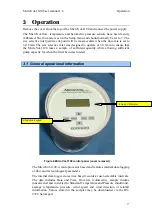
Страница 27: ...takes a sample of sufficient quantity while allowing sufficient pump capacity for when the filter becomes loaded 3 1 General operational information 4 line LCD display 6 function keypad Figure 6 Micro...

Страница 28: ...Is the current Day Of Week a specified sampling day Is the wind speed and direction sensor data within the programmed range Is the power supply voltage above the lower limit typically 11V If all of t...

Страница 29: ...tting the averaging period keep this in mind If you want to collect one day worth of data it will be necessary to set the Logger setup averaging period to at least 10 minutes If the averaging period i...

Страница 30: ...dd optional format Day SUN MON TUE YesNo YES NO Submenu When an editable menu operand is selected the following functions are available To move the cursor left or right use Page up or Select To change...

Страница 31: ...s current flow rate Displays current temperature Displays current barometric pressure Figure 7 Main screen pump on Auto Manual 20 09 05 Sampling 11 53 23 Flow l min 3 000 Temp C 22 90 Press mmHg 763 4...

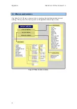
Страница 32: ...er manual 1 6 3 3 Menus and screens The MicroVol 1100 uses a menu system to organise the operating parameters and settings The layout of the menu system is straightforward and easy to learn Figure 10...

Страница 33: ...sample volume corrected to STP Displays sampling duration pump running Displays current power supply voltage Displays pump load 0 000 2 000 Displays current day of the week Is current time date combi...

Страница 34: ...nes what happens when the filter blocks up and the flow rate can no longer be maintained at the set value Setting this parameter to YES activates low flow rate limits As the filter loading increases t...

Страница 35: ...sday etc which commences at the programmed Start Date and will continue until the End Date is reached All conditions must be met for the sampling to commence so make sure that the Start Date End Date...

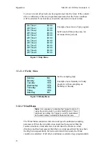
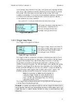
Страница 36: ...hows Monday to Friday program with no sampling on Saturday or Sunday Sunday NO Monday YES Tuesday YES Wednesday YES Thursday YES Friday YES Saturday NO Figure 18 Weekly Menu 3 3 2 2 Wind Menu Note It...

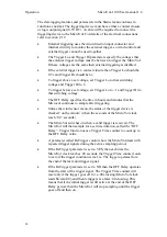
Страница 37: ...terfere with the Trigger program for example Times and Wind settings Likewise if external triggering is not required set the trigger parameters so that they do not interfere with other programs The ex...

Страница 38: ...pecifies the time in hours and minutes that the Microvol continues to sample after triggering Unlike the wind sensor menu the status of the trigger device is checked on the minute when the seconds of...

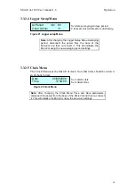
Страница 39: ...croVol and then re connect it This will initialise the MicroVol using the new averaging period settings 3 3 2 5 Clock Menu The Clock Menu sets the MicroVol clock Note that times should be entered in 2...

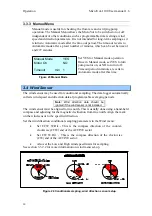
Страница 40: ...1 Figure 23 Manual Mode 3 4 Wind Sensor The wind sensor may be used for conditional sampling The data logger automatically collects wind speed and direction data at programmable averaging periods Not...

Страница 41: ...ases the time that the rainfall occurred can be worked out The MicroVol data logger increments each time the rain gauge bucket tips The data value increases until the data logger is reset using the Se...

Страница 42: ......

Страница 43: ...til the MicroVol temperature is close to the actual temperature 4 2 Barometric Pressure Sensor Calibration 1 Record the barometric pressure displayed by the MicroVol 2 Record the actual barometric pre...

Страница 44: ...w meter 3 Repeat steps 1 and 2 with a different flow rate Flow rates of 2 0 litres min and 3 0 litres min are recommended Record the results in a table see below If the MicroVol and actual values are...

Страница 45: ......

Страница 46: ...this port Connect the other end of the cable to your computer If your computer has a 25 pin male serial port you may need to use a DB9 M DB25 F adaptor or the appropriate 9 pin to 25 pin cable 5 1 Us...

Страница 47: ...er the settings menu through the properties under the Comm menu or by clicking the following icon In the Output file box type the directory pathname and filename for the data file to be created Figure...

Страница 48: ...ram such as Microsoft Excel by specifying that the data is delimited using comma delimiters Using this method the data will be formatted into individual cells The data is presented in the following fo...

Страница 49: ...te 5 2 Communicating with the MicroVol alternative method An alternative more complicated way of downloading data is to use a terminal emulator Send EA command then use terminal to download file using...

Страница 50: ...mbient and Reference temperature and pressure information the sample volume is automatically corrected to Standard Temperature and Pressure STP conditions The MicroVol s internal data logger stores bo...

Страница 51: ...ass concentration calculation Mass concentration MC is calculated using the formula V W W MC i f where Final mass of filter element Wf Initial mass of filter element Wi V Sample volume either correcte...

Страница 52: ...ty and environmental conditions 6 3 Maintenance procedures 6 3 1 Cleaning the inlet components A regular routine should be devised to ensure that the sampler is functioning as it was designed to This...

Страница 53: ...ould be greased lightly in the centre masking the outer part of the disc so that the grease is only in the centre of the impaction plate covering an area about 10mm in diameter Light petroleum grease...

Страница 54: ...um and pressure on the appropriate ports If there appears to be a problem disconnect the pump terminals from the circuit board cut the ties that secure the pump and remove the pump from the sampler Ea...

Страница 55: ...ature calibration coefficient 0 Temperature calibration coefficient 1 Baro pressure calibration coefficient 0 Baro pressure calibration coefficient 1 Wind speed calibration coefficient 0 Wind speed ca...

Страница 56: ......

Страница 57: ...uts down the pump automatically when supply voltage drops below 11V nominal This feature protects the battery from damage The MicroVol display and data collection continues to operate until the batter...

Страница 58: ......

Страница 59: ...about 5V after a period of several days Ideally the battery should be recharged well before this as the battery may be damaged 8 1 1 Charging the battery pack The battery pack must be charged in a ven...

Страница 60: ...tlet when connecting and disconnecting the battery The charging time will vary depending on the initial charge state of the battery When the indicator lamp is green the battery is fully charged The un...

Страница 61: ...ockwise direction 2 turns is sufficient Figure 30 Dual stage filter holder 8 3 PM2 5 Nozzle Adaptor option Figure 31 Views of the PM nozzle adaptor pencil shows scale 2 5 The PM2 5 nozzle adaptor is d...

Страница 62: ...led With the filter holder connecting tube and impactor plate removed carefully insert or remove the PM2 5 nozzle adaptor in the nozzle body The nozzle body with the PM nozzle adaptor installed 2 5 Fi...

Страница 63: ...ump P ECO MICRO10006 S Replacement Flow sensor P ECO MICRO10007 S 50x 47mm Filters 2 0um P ZRU 10 002322 0050 Battery pack P ECO MICRO11001 O Battery charger 240V P ECO MICRO10002 O Battery charger wi...

Страница 64: ...tion flow rates l min Log book entry date time Sampling location or address Calibration device ID number Calibration temperature error Sample start date time Elapsed RunTime minutes Corrected volume S...

Страница 65: ...This page is intentionally blank...

Страница 66: ...change without notice Images used are for illustrative purposes only All trademarks and registered trademarks are the property of their respective owners 2022 Acoem and all related entities All right...

Страница 67: ......
Отзывы:

Похожие инструкции для LVS-100