Getting Started
MEN Mikro Elektronik GmbH
18
20G020-00 E5 – 2014-01-21
1
Getting Started
This chapter gives an overview of the board and some hints for first installation in a
system.
1.1
Map of the Board
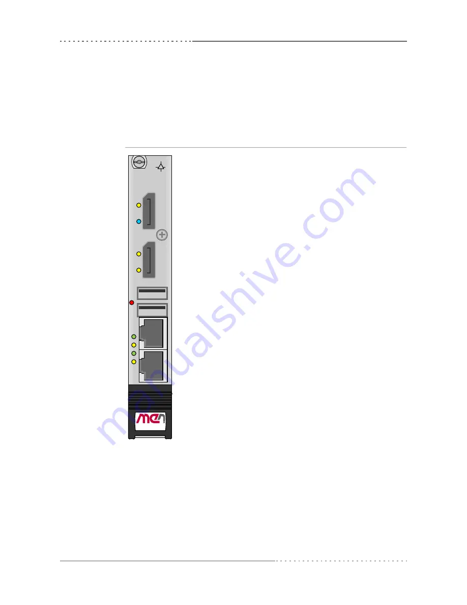
Figure 1.
Map of the board – front panel
G20
DP 2
3
4
DP 1
1
2
RST
®
CompactPCI
Serial


