


Functional Description
MEN Mikro Elektronik GmbH
45
20A014-00 E2 – 2007-08-16
2.12
GPIO
Five GPIO controllers are included in the FPGA. Each of them controls eight I/O
signals, totalling 40 signals. One of these signals is fixed to a specific function:
GPIO2.4 is used as push-button reset input. This leaves 39 completely user-
definable lines.
All pins are
directly
connected to the FPGA. Voltage levels are LVTTL.
You can control the GPIO lines through software using MDIS4 driver software
available on MEN’s
website
. The following table gives the assignment of the GPIO
controllers implemented in the A14C’s FPGA to their function on the board.
Normally you can identify the controllers by their instance numbers in your
operating system.
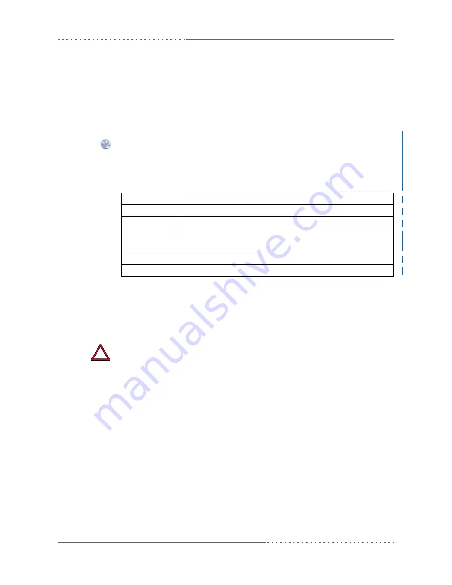
Table 13.
Assignment of 16Z034_GPIO controllers
The GPIO signals are available via rear I/O on connector P2. For the pin assignment
please see
Table 30, Pin assignment of VMEbus rear I/O connector P2 – FPGA I/O
signals, on page 80
.
Since all of the GPIO signals are controlled by the FPGA, you could also use the
respective pins on P2 to implement other rear I/O functions in FPGA instead of
GPIO. Please
contact MEN’s sales team
if you have special needs.
Please note that PMC I/O signals are directly connected to connector P2. If you
use GPIO I/O signals via P2, you must make sure that these signals do not
interfere with PMC I/O signals, since this may cause damage to the CPU
board.
See
Chapter 2.16.16.1 Rear I/O using VMEbus P2 on page 77
for more
details and for pin assignments of P2.
Instance
Function
0
GPIO lines 0.0 to 0.7 (bits 0..7)
1
GPIO lines 1.0 to 1.7 (bits 0..7)
2
GPIO lines 2.0 to 2.7 (bits 0..7)
GPIO2.4 is used for push button reset
3
GPIO lines 3.0 to 3.7 (bits 0..7)
4
GPIO lines 4.0 to 4.7 (bits 0..7)
!


