background image

Rev 1.4

Mellanox Technologies

59

8. Montaje y mantenimiento de bastidores 

9. Instalación de equipos 

10. Asegurar confinamientos adecuados 

11. Eliminación de equipos  

12. Códigos eléctricos locales y nacionales 

13. Cable de alimentación homologado por UL y con certificación CSA   Fuga > 3,5 mA 

Al instalar o realizar el mantenimiento de este aparato en un bastidor, es preciso 
adoptar precauciones especiales para garantizar que el sistema se mantenga 
estable. En general, en un bastidor, los equipos se deben instalar comenzando 
desde abajo hacia arriba.

La instalación, el reemplazo y el mantenimiento de este equipo estarán a cargo 
únicamente de personal capacitado y competente.

El fabricante del producto final o el usuario final deberán suministrar 


un confinamiento adecuado para componentes eléctricos y mecánicos y contra incen-
dio.

La eliminación definitiva de este equipo se debe efectuar conforme a todas las leyes y 
reglamentaciones nacionales.

Este equipo se debe instalar conforme a los códigos eléctricos locales y nacionales.

En conexiones de América del Norte, seleccionar un cable de alimentación 
homologado por UL y con certificación CSA de tres conductores, [16 AWG], termi-
nado en un enchufe moldeado con capuchón de 125 voltios nominal, [13 A], con una 
longitud mínima de 1,5 metros, pero no más de 4,5 metros.

En conexiones europeas, seleccionar un cable de alimentación armonizado 


internacionalmente y marcado "<HAR>", de tres conductores, hilo de 1,0 mm2 como 
mínimo, 300 voltios nominal, con cobertura protectora aislante de PVC. El cable debe 
tener un enchufe moldeado con capuchón de 250 voltios nominal, 10 A.

ADVERTENCIA: Alta corriente de fuga. Es esencial efectuar la conexión a tierra 
antes de conectar la alimentación.

Содержание BridgeX BX5020 GT Series

Страница 1: ...www mellanox com BridgeX GT Series BX5020 Gateway IB to Ethernet User Manual P N MBX5020 1SFR Rev 1 4 ...

Страница 2: ...OMER IN TESTING APPLICATIONS THAT USE THE PRODUCTS IN DESIGNATED SOLUTIONS THE CUSTOMER S MANUFACTURING TEST ENVIRONMENT HAS NOT MET THE STANDARDS SET BY MELLANOX TECHNOLOGIES TO FULLY QUALIFY THE PRODUCT S AND OR THE SYSTEM USING IT THEREFORE MELLANOX TECHNOLOGIES CANNOT AND DOES NOT GUARANTEE OR WARRANT THAT THE PRODUCTS WILL OPERATE WITH THE HIGHEST QUALITY ANY EXPRESS OR IMPLIED WARRANTIES INC...

Страница 3: ...Other Formats 15 2 2 5 Status LEDs 16 2 2 6 Port Connector LEDs 19 2 2 7 Reset Button 19 2 2 8 Air Flow 20 2 2 9 Management Interfaces 21 2 3 Package Contents 22 2 4 Gateway Installation and Operation 22 2 4 1 Installation Safety Warnings 23 2 4 2 Mechanical Installation 26 2 4 3 Grounding the Gateway 30 2 4 4 Disassembling the Gateway from the Rack 30 2 4 5 Power Connections and Initial Power On ...

Страница 4: ...ering Numbers 50 Appendix E Avertissements de sécurité d installation French 52 Appendix F Installation Sicherheitshinweise German 55 Appendix G Advertencias de seguridad para la instalación Spanish 58 Appendix H SFP Modules 62 H 1 Product Features 62 H 2 Applications 62 H 3 Dimensions 62 H 4 Pin Descriptions 63 H 5 Power Dissipation 64 ...

Страница 5: ...teway Port Grouping Protocols and Speeds 13 Table 6 System Status LED Configurations 17 Table 7 Fan LED Configurations 17 Table 8 PSU Status LED Configurations 18 Table 9 Port Connector LED Assignment 19 Table 10 Air Flow Direction 20 Table 11 Gateway and Installation Kit Options 26 Table 12 BX5020 1S Specification Data 41 Table 13 SFP Pinout 44 Table 14 Replacement Parts Ordering Numbers 50 Table...

Страница 6: ...nagement Interfaces 21 Figure 14 Installation Kit Parts 27 Figure 15 Making Room for the Power Cord 28 Figure 16 Screwing on the Bracket 28 Figure 17 Screwing on the Rail 28 Figure 18 Clipping in the Caged Nuts 29 Figure 19 Caged Nut Locations 29 Figure 20 Ground Connection 30 Figure 21 Two Power Inlets Electric Caution Notifications 32 Figure 22 PSU Pulled Out 33 Figure 23 Top and Bottom Ports 34...

Страница 7: ...Revision History Table Date Revision Description August 2011 1 4 Updated Power numbers Added Power as heat in BTUs hr June 2011 1 3 Removed references to FC June 2011 1 2 Minor fixes Feb 2011 1 1 New power numbers New I2C section Sept 2010 1 0 Initial release ...

Страница 8: ...cal Area Network LAN switch facing ports where Ethernet EN are used Table 2 Reference Documents BridgeX Programmer s Reference Manual Document 2936PM User guide describing the interface used by developers to write a driver between system software and the Mellanox BridgeX device FabricIT BX Management Software CLI User s Manual User manual describing the software interface including examples for us...

Страница 9: ...QSFP uplink ports and 16 SFP downlink ports with CPU RoHS6 Place Field Decoder M Mellanox Technologies BX System Type BridgeX based Bridge System 1 Gateway protocols 1 Ethernet Uplinks 5 InfiniBand Uplinks 9 VPI Ethernet and InfiniBand Uplinks 0 For future use 2 of BridgeX devices 1 For future use 2 2 BridgeX devices 0 For future use Separator 1 Power Supplies 1 1 2 2 M Depth of the Unit S standar...

Страница 10: ...puting HPC applications to Ethernet LAN ConnectX and ConnectX 2 adapters also present a standard InfiniBand Verbs software interface to server applications for Inter Process Communication IPC This allows Ethernet and InfiniBand payloads to be carried over a common converged high performance 40Gbps InfiniBand fabric without any changes to existing server applications Data on the converged fabric re...

Страница 11: ...NICs per Ethernet port Total of 16 000 MAC addresses Ethernet ports IEEE 802 3ae 10Gigabit Ethernet support IEEE 802 3z Gigabit Ethernet IEEE 802 1D Spanning Tree IEEE 802 1p QoS COS IEEE 802 1Q VLAN Tagging IEEE 802 1AB Link Layer Discovery IEEE 802 3ad Link Aggregation with LACP IEEE 802 3x Flow Control Per Priority Flow Control Virtual lanes support Jumbo Frames up to 9K support This feature wi...

Страница 12: ...connector IB ETH side of the gateway on the bottom right hand side See Figure 3 on page 12 for a sample of the product label See Figure 1 on page 10 for the product label tab location Figure 3 Generic Product Label 1 3 Gateway Port Groups There are four gateway groups in the BX5020 identified as A B C and D Each gateway group consists of one QSFP uplink port and four SFP down link ports Each gatew...

Страница 13: ...EN IB EN 10 20 40 G bps G a te w a y G rou p B 1 0G bp s 1G bp s 1 0G b ps 1 0G bp s unu sed 1G b ps 1G bps unu sed U plink D o w n lin ks EN IB EN 10 20 4 0 G bp s G a tew ay G ro u p C 1 0G bp s 1G bp s 1 0G b ps 1 0G bp s unu sed 1G b ps 1G bps unu sed U plink D o w n lin ks EN IB EN 10 20 4 0 G bp s G a te w a y G rou p D 1 2 3 4 5 1 2 3 4 5 1 2 3 4 5 STATUS PSU 1 PSU 2 FAN RST A B C D EN FC E...

Страница 14: ...ctor IB ETH side Figure 5 Gateway System Connector and Power Side Panels All connectivity is via the connector panel All connectors can support active cables 2 2 1 Downlink Ports There are four downlink ports per gateway port group These ports have SFP connectors that sup port both direct attach copper cables and optical cables by using SR or LR modules When configured for Ethernet only 3 of the 4...

Страница 15: ...side The following downlink options are also supported SFP modules for 1 10GbE 2 2 4 1 SFP Transceiver Module The gateways are shipped without optical modules Approved Mellanox modules must be pur chased from Mellanox The OPNs for the approved Mellanox modules are MFM1T02A SR and MFM1T02A LR The figure below shows the Mellanox approved SFP module Figure 6 SFP Transceiver Module 2 2 4 2 Inserting t...

Страница 16: ...by opening the handle 2 Pull the module out of the cage 2 2 5 Status LEDs Figure 9 Power and System LEDs 2 2 5 1 System Status Indicators Status indicators are located on the right side of power side panel and on the left side of the con nector IB ETH side panel Both of these system status indicators are three color LEDs display ing the same status on both sides of the gateway The following status...

Страница 17: ... to the gateway Turn off immediately For example bad FW can t boot or overheated Note When the system is turned on the red LED will light up for up to two minutes until the CPU is up and running Off Off The system has no power If the STATUS LED shows red after five minutes unplug the gateway and call your Mellanox representative for assistance If the FAN LED shows red troubleshoot the fan module I...

Страница 18: ...Each PSU also has a single 2 color LED to the right of the PSU that indi cates the internal status of the unit PSU status indicators are also located on the left side of the connector IB ETH side panel and labeled PSU1 and PSU2 Table 8 Shows the explanation of the PSU Status LED colors All fans must be operating while the power supply is plugged in If the gateway shuts down due to over temperature...

Страница 19: ...s showing green and the second PSU is unplugged it will show a red indication Table 9 Port Connector LED Assignment LED LED Description Off No power to the port Solid Green Logical link up Flashing Green Data activity flashing speed data transfer speed Orange Physical link up Flashing Orange A problem with the physical link DO NOT use a sharp pointed object such as needle or push pin for pressing ...

Страница 20: ...r Flow These gateways can come with two air flow patterns The two patterns are connector IB ETH side inlet to power side outlet Power side inlet to connector IB ETH side outlet The air flow is specified in the product model number See Mellanox Part Numbering Legend on page 9 On the PSUs and fan modules the air flow direction can be seen on the power side panel Table 10 Air Flow Direction Picture O...

Страница 21: ...gateway For the initial configuration procedure for the gateway see the Installation Guide 2 2 9 2 GigE Ethernet Connector The gateway has two Ethernet connectors This Ethernet connection provides access for remote management The BX series gateways can be connected to a network through the RJ45 connectors There are two GigE connectors Their MAC addresses can be found on the product version label F...

Страница 22: ...ttention to the normal mechanical power and thermal precautions for rack mounted equipment The gateway requires programming and configuration to operate as a basic InfiniBand to Ethernet gateway The gateway includes all of the necessary functionality to operate with external standard Subnet Management software This section describes the installation process and basic operation of the gateway Pleas...

Страница 23: ...oards power supplies and fan tray modules for proper insertion before plugging in a power cable Read all installation instructions before connecting the equipment to the power source This equipment should not be operated in an area with an ambient temperature exceed ing the maximum recommended 45 C 113 F Moreover to guarantee proper air flow allow at least 8cm 3 inches of clearance around the vent...

Страница 24: ...eakage current Earth connection essential before connecting sup ply Before connecting this device to the power line the protective earth terminal screws of this device must be connected to the protective earth in the building installation This device must be installed according to the latest version of the country national electrical codes For North America equipment must be installed in accordanc...

Страница 25: ...nd EN 60825 1 1994 A1 1996 A2 2001 For North American power connection select a power supply cord that is UL Listed and CSA Certified 3 conductor 18 AWG terminated in a molded on plug cap rated at 125 V 15 A with a minimum length of 1 5m six feet but no longer than 4 5m For European connection select a power supply cord that is internationally harmonized and marked HAR 3 conductor minimum 0 75 mm2...

Страница 26: ... kit that fits your needs Table 11 Gateway and Installation Kit Options 2 4 2 2 Installing the Gateway in the Rack Tools required and customer supplied parts Parts included in the rail kit The rack mounting holes conform to the EIA 310 standard for 19 inch racks Take pre cautions to guarantee proper ventilation for air intake at the front of the chassis and exhaust at the rear in order to maintain...

Страница 27: ...r visible damages that may have occurred during shipping 2 Screw the brackets onto the gateway Use 3or 4 depending on the bracket position flat head screws to connect each bracket to the gateway 2 brackets 8 pan head screws M6 If anything is damaged or missing contact your customer representative immediately If you need room to bring the power cord from the other side of the rack recess the gatewa...

Страница 28: ...connect the rail slides Check that both sides of the gateway left and right are the same level in the rack The side of the gateway with these brackets will be the side that is even with or close to the vertical rack support Power cord Place to run the power cable In this position you will use 4 flat head screws In this position you will use 3 flat head screws In this position the front of the gate...

Страница 29: ...rt 8 Slide the gateway catching the rail slides into the rails on the gateway If you extended the bracket past the gateway to use the slot for the power cord now is the time to put the power cord through the slot 9 Screw in the bolts into the caged nuts and tighten the bolts to 9 2 Nm or 81 5 pound inches 10 Ground the gateway See Section 2 4 3 for grounding instructions 11 Plug in the power cord ...

Страница 30: ...ound screw make sure that the rack is properly grounded and that there is a valid ground connection between the chassis of the gateway and the rack Test the ground using an Ohm meter Figure 20 Ground Connection Check to determine if your local or national electrical codes require an external ground to all IT components 2 4 4 Disassembling the Gateway from the Rack To disassemble the gateway from t...

Страница 31: ...ompatible with the electrical system of your country Support the gateway while you unscrew the last screw The gateway will drop and could become damaged or it could damage other equipment in the rack Caution The gateway will automatically power on when AC power is applied There is no power switch Check all boards power supplies and fan tray modules for proper insertion before plugging in a power c...

Страница 32: ...er supply unit when there is only one working PSU in the gateway If the Gateway is powered off for any reason without using the proper shut down pro cedure the Flash memory may be corrupted If the Flash memory is corrupted the Gateway may fail to boot Should this happen call your Mellanox representative for assistance Make sure that the PSU that you are NOT replacing is showing all green for both ...

Страница 33: ...r 5 Insert the other end of the power cord into an outlet of the correct voltage 2 4 8 Cable Installation All cables can be inserted or removed with the unit powered on To insert a cable press the con nector into the port receptacle until the connector is firmly seated The indicator above each port will light green when the physical connection is established that is when the unit is powered on Pow...

Страница 34: ...y around to the side of the chassis before bending upward or downward in the rack These gateways are able to support direct attached copper cables optical FC cables and cables with media adapters at various lengths and gauges Check www mellanox com Products Cables for cable recommendations regarding Mellanox approved cables and recommended maxi mum cable lengths Cables in the bottom row should be ...

Страница 35: ... To extract a Fan Unit Fan Module Latches Figure 24 Fan Unit Pulled Out 1 Using two hands push both latch releases in simultaneously while pulling the fan module out of the gateway As the fan unseats the fan status indicator will turn off 2 Pull the fan unit out Operation without a fan unit should not exceed one minute During fan hot swap if the LED indicators are OFF then the fan unit is disconne...

Страница 36: ...ance is felt Continue press ing the fan unit until it seats completely Make sure that the new fan unit has the correct air flow direction This can be verified by checking the label on the fan unit and comparing it to the air flow label on the PSU The green fan status indicator should light If not extract the fan unit and reinsert it After two unsuccessful attempts to install the fan unit power off...

Страница 37: ... the gateway system via FabricIT 3 1 FabricIT FabricIT is a software based management system that can be run with either a command line inter face or with a GUI interface The GUI interface can be run through the Web See the FabricIT BXM User Manual for instructions and commands available to manage the gate ways and fabric To access this document download the User Manual from www mellanox com Produ...

Страница 38: ...blocking the front or rear of the chassis and that the fan mod ules and ventilation holes are not blocked especially dust over the holes 3 Use the FabricIT BXM manager to check the temperature of the gateway 4 If you find dust blocking the holes it is recommended to clean the fan unit and remove the dust from the front and rear panels of the gateway using a vacuum cleaner The green power LED for t...

Страница 39: ... Choose the image to upload Only use image 1 or image 2 U Boot 2009 01 mlnx1 4 May 12 2010 14 08 15 CPU AMCC PowerPC 460EX Rev A at 1000 MHz PLB 200 OPB 100 EBC 100 MHz Security Kasumi support Bootstrap Option H Boot ROM Location I2C Addr 0x52 Internal PCI arbiter disabled 32 kB I Cache 32 kB D Cache Board Mellanox PPC460EX Board FDEF No I2C ready DRAM 2 GB ECC enabled 400 MHz CL3 FLASH 16 MB NAND...

Страница 40: ...shooting Rev 1 4 Mellanox Technologies 40 Boot Menu 1 EFM_PPC_M460EX EFM_1 1 1000 2010 06 24 16 32 03 ppc 2 EFM_PPC_M460EX EFM_1 1 1200 2010 06 25 18 00 03 ppc 3 U Boot prompt Choice 5 Select the image to boot ...

Страница 41: ...liance InfiniBand QoS Management ETHERNET PORTS Auto Negotiation of 40Gb s 20Gb s 10Gb s 8 InfiniBand Virtual Lanes for all ports Baseboard Performance and Device management Agents for full InfiniBand In Band Management Ethernet over InfiniBand EoIB proto col encapsulation IEEE 802 3ae 10 Gigabit Ethernet IEEE 802 3z Gigabit Ethernet IEEE 802 1D Spanning Tree IEEE 802 1p QoS COS IEEE 802 1Q VLAN T...

Страница 42: ...lity Features Switching Perfor mance Addressing Bridging Capacity Simultaneous wire speed any port to any port 48K Unicast Addresses Max per Subnet 16K Multicast Addresses per Subnet 320Gb s Hot Swappable 1 1 Redundant Fan Module and Power Sup plies Power Supplies Table 12 BX5020 1S Specification Data ...

Страница 43: ...rtifications The list of approved certifications per gateway in different regions of the world is located on the Mellanox Website at www mellanox com related docs user_manuals Regulatory_and_Compliance_Guide pdf EMC Statements are also in the Regulatory and Compliance Guide ...

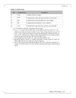
Страница 44: ... Line d 6 MOD_ABS Module Absent Grounded within the module d 7 RS0 No connection required 8 RX_LOS Loss of Signal indication Logic 0 indicates normal operation e 9 RS1 No connection required 10 VeeR Receiver Ground Common with Transmitter Ground a 11 VeeR Receiver Ground Common with Transmitter Ground a 12 RD Receiver Inverted DATA out AC Coupled 13 RD Receiver Non inverted DATA out AC Coupled 14 ...

Страница 45: ...be between 2 0V to Vcc 0 3V A high output indicates a transmitter fault caused by either the TX bias cur rent or the TX output power exceeding the preset alarm thresholds A low output indicates normal operation In the low state the output is pulled to 0 8V c Laser output disabled on TDIS 2 0V or open enabled on TDIS 0 8V d Should be pulled up with 4 7kΩ 10kΩ on host board to a voltage between 2 0V...

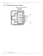
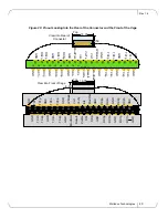
Страница 46: ...ox Technologies 46 C 2 RS232 to RJ45 Connector Interface Figure 26 RJ45 Connector Pinout TXD TXD RXD GND GND RXD GND GND RJ45_RTS RJ45_DTR RJ45_TXD GND GND RJ45_RXD GND GND Pin 1 Pin 8 Looking into the Socket CONSOLE ...

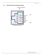
Страница 47: ...1 4 Mellanox Technologies 47 C 3 I2C RJ45 Connector Interface Pinout Figure 27 I2C Pinouts TXD TXD RXD GND GND RXD GND GND RJ45_SDA GND GND GND GND RJ45_SCL GND GND Pin 1 Pin 8 Looking into the Socket I2 C ...

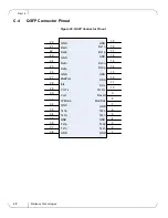
Страница 48: ...GND Rx2n GND 1 2 3 4 5 6 7 8 9 10 11 12 13 14 15 16 17 18 19 20 21 22 23 24 25 26 27 28 29 30 31 32 33 34 35 36 37 38 Rx1n Rx2p Rx1p GND GND GND GND GND GND Tx2n Tx1n Tx2p Tx1p Tx4n Tx3n Tx4p Tx3p GND GND Rx4n Rx3n Rx4p Rx3p GND GND SDA SCL Vcc Rx ResetL ModSelL LPMode Vcc1 VccTx IntL ModPrsL ...

Страница 49: ...2 2 2 1 2 3 4 5 6 7 8 3 3 3 3 3 3 3 3 RX4p GND GND GND RX4n RX2p RX2n TX1n GND TX1p GND TX3n TX3p GND IntL ModPrsL VccTx Vcc1 LPMode 18 35 8 50 Top ResetL SDA SCL ModSelL RX3p TX2n GND VccRx 1 2 3 4 5 6 7 8 9 1 0 1 2 3 4 5 6 7 8 9 TX2p GND TX4n TX4p GND 1 1 1 1 1 1 1 1 1 1 20 GND GND GND RX3n RX1p RX1n 30 RX4p GND GND GND RX4n RX2p RX2n TX1n GND TX1p GND TX3n TX3p GND IntL ModPrsL VccTx Vcc1 LPMod...

Страница 50: ...ation kit Short gateway standard rack MIS000083 Rack installation kit short gateway short rack MIS000079 Harness RS232 to DB9 2M long cable HAR000028 Fan Unit for Power side to connector IB ETH side air flow MIS000051 Fan Unit for connector IB ETH side to Power side air flow MIS000082 Power cord Type C13 C14 ACC000251 Power cord Type B for USA Canada Mexico Taiwan ACC000204 Power cord Type H for I...

Страница 51: ...Rev 1 4 Mellanox Technologies 51 ...

Страница 52: ...libre autour des ouver tures de ventilation Le châssis ne doit pas être empilé sur un autre matériel Si le châssis tombe il peut pro voquer des blessures corporelles et des dégradations de biens Ce produit comporte un couvercle transparent sur l espace pour l alimentation élec trique redondante Ne pas faire fonctionner le produit si le couvercle transparent n est pas solidement fixé ou s il est en...

Страница 53: ...n Forts courants de fuite Il est essentiel de relier a la terre avant de brancher l alimentation Avant de brancher l appareil à la conduite d alimentation les vis de protection à la terre du terminal de l appareil doivent être appliquées à l installation de protection à la Terre du bâtiment Ce matériel ne doit être installé remplacé ou entretenu que par du personnel formé et qualifié L élimination...

Страница 54: ...ne exposition au rayonnement grave PRODUIT LASER DE CLASSE 1 et références aux normes laser les plus récentes CEI 60 825 1 1993 A1 1997 A2 2001 et NE 60825 1 1994 A1 1996 A2 2001 Des enceintes électriques mécaniques et incendie adaptées doivent être fournies par le fabricant du produit final ou par l utilisateur final Pour les prises électriques en Amérique du Nord choisissez un cordon électrique ...

Страница 55: ...andfreien Luftstrom zu gewährleisten Das Chassis sollte nicht auf andere Geräte gestapelt werden Wenn das Chassis herun terfällt kann es zu Verletzungen und Beschädigungen an Geräten führen Dieses Produkt verfügt über eine Abdeckung über dem Bereich für die redundante Stromversorgung Betreiben Sie das Produkt nicht wenn diese Abdeckung nicht sicher festsitzt oder entfernt wurde Arbeiten Sie währen...

Страница 56: ...rsteller des Endprodukts oder dem Endbenutzer bereitzustellen Achtung Nutzung von Steuerungen oder Einstellungen oder Ausführung von Proze duren die hier nicht spezifiziert sind kann zu gefährlichem Strahlenkontakt führen Klasse 1 Laserprodukt und Referenzen zu den aktuellsten Lasterstandards ICE 60 825 1 1993 A1 1997 A2 2001 und EN 60825 1 1994 A1 1996 A2 2001 Für Nordamerika Stromanschluss wähle...

Страница 57: ...uss an den Schutzleiter in der Gebäudeinstallation Dieses Gerät muss installiert sein entsprechend auf die neueste Version des Landes National Electrical Code Für Nordamerika müssen in Übereinstimmung mit den gel tenden Vorschriften in der US amerikanischen National Electrical Code und dem Canadian Electrical Code Kabel für den Anschluss an das Gerät RS232 und Ethernet Schnittstellen müssen UL zer...

Страница 58: ...erior a la máxima recomendada 45 C Además para garantizar una circulación de aire adecuada se debe dejar como mínimo un espacio de 8 cm 3 pulgadas alre dedor de las aberturas de ventilación Los chasis no se deben apilar sobre otros equipos La caída del chasis podría causar lesiones corporales así como daños al equipo Este producto incluye una fuente de alimentación redundante o en su lugar una vac...

Страница 59: ...o adecuado para componentes eléctricos y mecánicos y contra incen dio La eliminación definitiva de este equipo se debe efectuar conforme a todas las leyes y reglamentaciones nacionales Este equipo se debe instalar conforme a los códigos eléctricos locales y nacionales En conexiones de América del Norte seleccionar un cable de alimentación homologado por UL y con certificación CSA de tres conductor...

Страница 60: ...do al conductor de tierra de protección del edificio El equipo se instalará en un área donde haya conexión equipotencial como por ejemplo un centro de telecomunicaciones o una sala de computadoras dedicada Este dispositivo se debe instalar conforme a la versión más reciente de los códigos eléctricos nacionales del país en cuestión En América del Norte el equipo se debe instalar de acuerdo con las ...

Страница 61: ...2 96 CE sobre RAEE todos los residuos de equipos eléc tricos y electrónicos EEE se deben recolectar por separado y no se deben eliminar junto con residuos domésticos Al deshacerse de este producto y de todas sus partes hágalo de una manera responsable y respetuosa con el medio ambiente ...

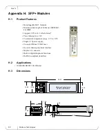
Страница 62: ...00 MHZ km MMF Supports 9 95 to 10 3 Gb s bit rates Power dissipation 1W Commercial temperature range 0 C to 70 C Single 3 3Vpower supply Uncooled 850nm VCSEL laser Receiver limiting electrical interface Duplex LC connector Built in digital diagnostic functions RoHS 6 compliant lead free Mellanox Technologies MTSFPP SR Module 14 80 13 60 56 50 13 70 13 90 11 85 1 80 1 55 44 95 8 50 2 55 0 50 0 60 ...

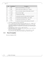
Страница 63: ...rface Data Line d 5 SCL 2 wire Serial Interface Clock Line d 6 MOD_ABS Module Absent Grounded within the module d 7 RS0 No connection required 8 RX_LOS Loss of Signal indication Logic 0 indicates normal operation e 9 RS1 No connection required 10 VeeR Receiver Ground Common with Transmitter Ground a 11 VeeR Receiver Ground Common with Transmitter Ground a 13 70 8 50 Top VeeT VeeT VeeT TX_Fault TX_...

Страница 64: ... output which should be pulled up with a 4 7k 10k Ohms resistor on the host board if intended for use Pull up voltage should be between 2 0V to Vcc 0 3V A high output indicates a transmitter fault caused by either the TX bias current or the TX output power exceed ing the preset alarm thresholds A low output indicates normal operation In the low state the output is pulled to 0 8V c Laser output dis...

Отзывы: