Rev 1.4
Mellanox Technologies
19
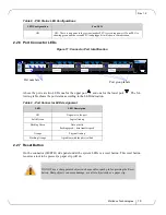
2.2.6 Port Connector LEDs
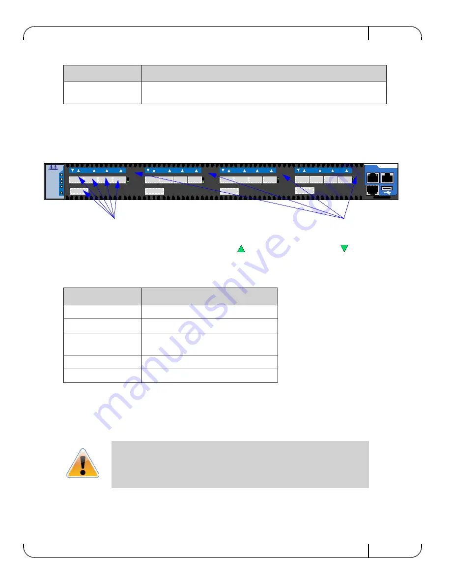
Figure 11: Connector Port Identification
Above the ports are two LEDs one for the upper port
and one for the lower port
. The fol-
lowing table shows the port status according to the LED indication.
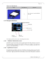
2.2.7 Reset Button
On the connector (IB/ETH) side panel under the system LEDs is a reset button. This reset button
requires a tool to be pressed, a paper clip will do.
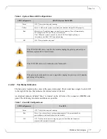
Off
Off – There is no power to the system (neither PSU is receiving power). If one PSU is
showing green and the second PSU is unplugged it will show a red indication.
Table 9 - Port Connector LED Assignment
LED
LED Description
Off
No power to the port.
Solid Green
Logical link up
Flashing Green
Data activity
flashing speed
≈
data transfer speed
Orange
Physical link up
Flashing Orange
A problem with the physical link
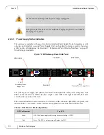
DO NOT use a sharp pointed object such as needle or push pin for pressing the Reset
button. Sharp objects can cause damage, use a flat object such as a paper clip.
Table 8 - PSU Status LED Configurations
LED Configuration
Fan LED
STATUS
PSU 1
PSU 2
FAN
RST
< A
< B
EN
FC
EN
FC
MGT CONSOLE
MBX5020
1
2
3
4
5
< C
EN
FC
< D
EN
FC
1
2
3
4
5
1
2
3
4
5
1
2
3
4
5
Port group labels
Port numbers


