
5 8
S V E R K E R 7 5 0 / 7 6 0
P r o g r a m m a E l e c t r i c A B
Z P - C D 0 1 E R 0 5 A
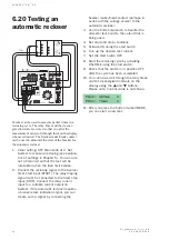
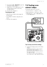
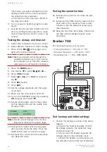
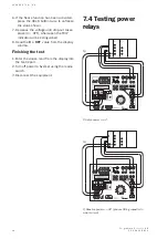
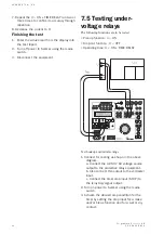
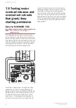
(the resistor you select will depend on the
testing current) to the current input (NI) to
the protective relay equipment.
d. Connect the timer stop input (STOP) to
the relay trip output.
2.
Turn on power to Sverker using the mains
switch.
3.
Activate the desired stop condition for the
timer by setting the stop input for a make
and/or break function and for a wet or dry
contact.
Testing the pick-up and drop-out
1.
Select stop conditions, dry or wet contact.
2.
Select HOLD to freeze the current reading.
3.
Press button
SEL
/
until you get a red
light at the built-in ammeter.
Note!
Maximum allowed current through the
separate ammeter used in this connec-
tion example is 6 A. The other measure-
ment points do not have this limitation.
4.
Press the
MODE
button.
5.
Use the key
W
to select
Ω
Ω
Ω
Ω
Ω
,
ϕϕϕϕϕ
, W, VA....
6.
Press
CHG
(Change)
7.
Select
ϕ
ϕ
ϕ
ϕ
ϕ
(°, Iref)
or (
°, Uref
) by using the
key
W
.
8.
Press
SEL
(Select)
9.
Press
ESC
10. Set the voltage amplitude with the upper
small knob.
11. Make sure the main knob is set to
0
.
12. Turn on the SVERKER output by activating
ON
using the start switch
W
.
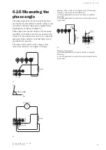
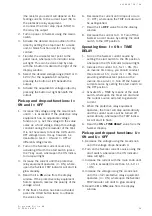
13. Set the phase-angle. Use the lower knob
for fine adjustment, and the middle knob
for step of 90
°.
000ms
070°
0.100A
63.05V
Note!
A small current flowing in the circuit is
required to measure the phase angle.
14. Increase the current until the relay oper-
ates (pick-up). Read the value. Press the
HOLD button twice to reset the display.
15. Decrease the current until the relay drops
out. Read the value.
Testing the operation time
16. Increase the current to 1.5 times the pick-
up value.
17. Invoke the ON+TIME state by means of the
start switch. The outputs will now remain
turned on until the protective relay equip-
ment operates.
18. Read the time from the display. Check also
the high current setting using the same
procedure.
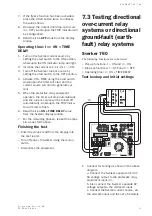
Sverker 750
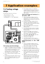
The following functions are to be tested:
• Pick-up functions: I > ON and U > ON
• Drop-out functions: I > OFF and U > OFF
• Operating time: I > ON + TIME DELAY
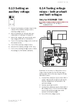
Test hookup and initial settings
1.
Connect for testing as shown in the above
diagram.
a. Connect the Sverker separate 0-120 V
AC voltage output to the protective relay
equipment input (U).
b. Also connect the Sverker separate AC
voltage output to the voltmeter input.
c. Connect the Sverker current source, via
the ammeter input and the set of resistors
Содержание Programma Sverker 750
Страница 1: ...SVERKER 750 760 User s manual Relay Test Unit ...
Страница 28: ...2 9 S V E R K E R 7 5 0 7 6 0 P r o g r a m m a E l e c t r i c A B Z P C D 0 1 E R 0 5 A ...
Страница 75: ...7 6 S V E R K E R 7 5 0 7 6 0 P r o g r a m m a E l e c t r i c A B Z P C D 0 1 E R 0 5 A ...
Страница 76: ...Subject to change without notice Printed matter ZP CD01E R05B 2007 ...


