background image

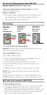
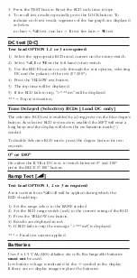
3. Press the TEST button. Reset the RCD each time it trips.
4. To recall test results repeatedly press the LOCK button. To 

indicate each test result, segments of the bar graph are displayed 
as below:
no bars = 

1/2

I

test, one bar =  

I

test, five bars = 

5I

test

DC test [DC]

Test Lead OPTION 1,2 or 3 as required

1) Select the appropriate RCD rated current on the rotary switch.

2) Select 

1/2

I

I

or 

5I

on the left hand rotary switch.

3)  Use the BLUE button to cycle through the test options, selecting 

DC and the polarity of the test (0º/180º).

4) Press the YELLOW test button.

5) The trip time will be displayed.

5) If the RCD fails to trip, ">*** ms" will be displayed.

*** = Trip test duration.

Time Delayed (Selective) RCDs [I and DC only] 

The selective RCD test is enabled by a long press on the blue degree
button. As selective RCD test mode is enabled the MFT will emit a
long beep and the display will show the exclamation mark (!)
symbol.

To disable Selective RCD mode, press the degree button for two
seconds.

0º or 180º 

On either the 

I

, 5

I

or DC test, to switch between 0º and 180º 

press the BLUE 0°/180° button. 

Ramp Test [

]

Test Lead OPTION 1, 2 or 3 as required

A test current from 

1/2

I

to 

I

will be applied during which the 

RCD should trip.

1) Set the range select to the RAMP symbol.
2)  Set the RCD range switch [mA] to the current rating of the RCD.
3)  Press the YELLOW test button. 
4) Results are displayed in mA.
5) If RCD fails to trip the message ">***mA" is displayed.

*** = Final test current applied

Batteries

Uses 8 x 1.5 V AA (LR6) alkaline dry cells. Rechargeable batteries

must not

be used.

Low battery voltage is indicated by the

b

symbol in the display.

If there are no display images replace the batteries.

Содержание MFT1500/2

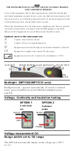
Страница 1: ...features and should not be regarded as a substitute for normal safe working practices Do not move the rotary switch positions while a test is in progress The LCD neon voltage indicators cannot reveal...

Страница 2: ...lectricians should be used Symbols used on the instrument are F Caution risk of electric shock G Caution refer to accompanying notes t Equipment protected throughout by Double Insulation Class II c Eq...

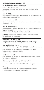
Страница 3: ...100 Warning Ensure the circuit to be tested is disconnected and isolated before starting testing Insulation testing M Range switch set to 250 V 500 V or 1 kV range Test Lead Options 1 or 2 For insulat...

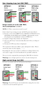
Страница 4: ...ed value may differ to the anticipated value This is caused by noise on the supply Repeating the test may result in a different reading if this is the case refer to page 13 of the handbook for possibl...

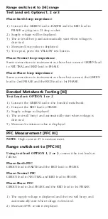
Страница 5: ...the RED lead to 1st PHASE Bonded Metalwork Testing Hi Test Lead set OPTION 1 or 2 1 Connect the GREEN lead to the bonded metalwork 2 Connect the RED lead to PHASE 3 Supply voltage is displayed 4 The...

Страница 6: ...Connect the test leads to the RCD as shown above 3 Press the YELLOW test button on the instrument or the switch probe On 1 2I the message 1999 ms is displayed after 2 seconds NOTE The message TrP will...

Страница 7: ...enabled by a long press on the blue degree button As selective RCD test mode is enabled the MFT will emit a long beep and the display will show the exclamation mark symbol To disable Selective RCD mod...

Страница 8: ...it 1 T 1 416 298 6770 Scarborough Ontario M1S 3R2 F 1 416 298 0848 Canada E casales megger com This instrument is manufactured in the United Kingdom The company reserves the right to change the specif...

Отзывы: