DET2/3
23
Test methods and set-up
Test methods and set-up
The test methods detailed in this section is not exhaustive, see the booklet '
Getting Down To Earth
' for more
information on other tests and methods.
Key to images in this section:
P: Potential spike
C: Current spike
E: Electrode
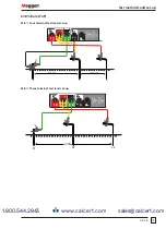
Fall of potential (FoP) test
Important:
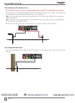
The current stake / pin, potential stake / pin and earth electrode must be placed in a straight line.
Important:
When running test leads out to each remote stake / pin, take care not to lay them close to each
other. This is to minimise the effect of mutual inductance.
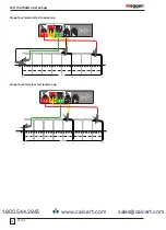
Four terminal test lead set-up
1. Insert the current stake / pin into the earth 30 to 50 metres away from the earth electrode to be tested.
2. Insert the potential stake / pin into the earth midway between the current test spike and the earth electrode.
3. Firmly connect terminal
C1
and
P1
to the earth electrode as shown.
4. Move the potential stake / pin three metres further away from the earth electrode and make a second
resistance measurement.
5. Move the potential stake / pin three metres nearer the electrode (than the original position) and make a third
resistance measurement.
If the three resistance readings are similar (within the required accuracy) then their average can be taken as the
resistance to earth of the electrode.
G
F
V
I
C1
E
E/X
CA
T
IV 300V
CA
T
IV 300V
CA
T
IV 300V
CA
T
IV 300V
Y
V
P1
ES
P2
S
C2
H
15 m to 25 m
15 m to 25 m
P1
P2
C2
www.calcert.com
1.800.544.2843
0
5
10
15
20
25
30


