DET2/3
26
Test methods and set-up
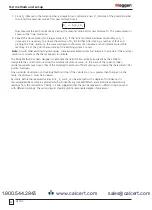
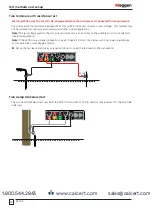
7. Since D
C
(distance to the current probe) is already known, calculate a new D
P
(distance of the potential probe)
then insert the potential probe at this new distance from E.
D
P
= D
P
/D
C
x D
C
Now measure the earth resistance by placing the potential probe at this new distance D
P
. This measurement is
known as the 'true' resistance.
8. Repeat the whole process for a larger value of D
C
. If the 'true' resistance decreases appreciably as D
C
is
increased, it is necessary to increase the distance of D
C
still further. After making a number of tests and
plotting the 'true' resistance, the curve will begin to show less of a decrease and will indicate more stable
readings. It is at this point the resistance of the earthing system is noted.
Note:
As with other earth testing techniques, some experimentation may be necessary to ascertain if the practical
result is as accurate as the theory appears to indicate.
The Slope Method has been designed to eliminate the need for impractically long leads by the ability to
interpolate the correct distance along the combined resistance curve, i.e. the curve of the current probe’s
resistance superimposed upon that of the tested grid, without sufficient spacing to produce the characteristic 'flat
portion' between.
One particular observation on the Slope Method is that if the calculation of μ is greater than that given in the
table, the distance C must be increased.
Secondly, before the measured values for R
1
, R
2
and R
3
can be accepted with a degree of confidence, it is
recommended that a curve be plotted which will identify any localized effects and eliminate uncharacteristic
readings from the calculations. Thirdly, it is also suggested that the test be repeated in different directions and
with different spacings. The various results should exhibit a reasonable degree of agreement.
www.calcert.com
1.800.544.2843
0
5
10
15
20
25
30


