A S 5 0 0 0 S E R V I C E M A N U A L
6
Chapter 3 Theory of Operation
Main Hydraulic Circuits
Circulation Circuit
– circulates temperature-controlled water
from the Circulation Tank through the
A
rctic
G
el
™
Pads and
returns to the inlet port of the Circulation Pump. The speed of
the Circulation Pump varies to maintain -7.0 PSI (0.5 bar) at
the Pressure Sensor. Since water in the
A
rctic
G
el
™
Pads flows
under negative pressure, a break in the circuit, such as a pad
being punctured or disconnected, will result in air leaking into the
system instead of water leaking out. Air in the system is removed
in the Circulation Tank and exits through the tank vent. When
warmer water is required, the heaters located in the Circulation
Tank are energized. The heater power is dependent upon the
flow rate through the circulation tank and the difference between
the water temperature and the commanded water temperature.
The heater has four elements that are cycled on sequentially to
minimize power fluctuations in the mains supply.
Chiller Circuit
– maintains the water in the Chiller Tank at
approximately 4°C. Water is gravity-fed into the centrifugal
Chiller Pump and is then pumped through the chiller’s evaporator
and returned to the Chiller Tank. The refrigerant system’s cooling
capacity is controlled by a refrigerant valve. When the Chiller
Circuit approaches 4°C, the cycling of the valve can be heard.
Mixing Circuit
– when cold water is required to cool the
Circulation Circuit, the Mixing Pump pulls water from the
Circulation Tank and meters it into the Chiller Tank. Cold water
overflows from the Chiller Tank into the Circulation Tank. The
speed of the mixing pump is dependent upon the flow rate
through the circulation tank and the difference between the water
temperature and the commanded water temperature.
Ancillary Hydraulic Circuits
Filling
– When filling, the Fill Valve is opened and water is drawn
up through the valve by the Circulation Pump. Water returns
through the Circulation Tank to the Supply Tank. Negative
Pressure must be generated at the inlet of the Inlet/Outlet
Manifold for filling to occur, therefore the Fluid Delivery Line must
be attached.
A
rctic
G
el
™
Pads should not be attached to the
Fluid Delivery Line during filling.
Preconditioning
– The system can be programmed to
precondition water prior to initiating therapy. In this mode, the
Bypass Valve opens and allows temperature-controlled water to
circulate internally to bring the Circulation Tank and Supply Tank
water to a pre-programmed temperature.
Empty Pads
– To empty water from the
A
rctic
G
el
™
Pads, the
Vent Valve is opened, which enables air to enter the pads. Water
is pulled from the pads by the Circulation Pump and returned
through the Circulation Tank to the Supply Tank.
Electronic Control System
The electronic system consists of two independent subsystems:
control and monitor. The control subsystem is responsible for
delivering therapy to the patient. The monitor subsystem confirms
the safe operation of the control subsystem. Each subsystem has
an independent microprocessor, audio alarm, and both water and
patient temperature sensing circuits.
The control subsystem performs the following functions:
• Command interpretation from the Control Panel
• System information update to the Control Panel
• Circulation Tank water temperature control (T1 & T2)
• Circulation Pump speed control from pressure sensor (P1)
• Patient temperature measurement (PT1)
• Temperature Out signal generation
• Chiller Tank water temperature control (T4)
• Valve control (VV, BV and FV)
• Chiller control
The monitor subsystem performs the following functions:
• Redundant command interpretation from Control Panel
• Circulation Tank temperature monitoring (T1)
• Patient temperature measurement (PT2)
• Circulation Pump power interrupt control
• Power Circuit Card voltage monitoring
Chapter 4 – Maintenance
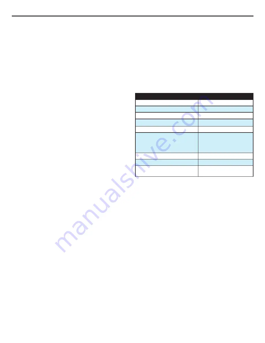
Maintenance Schedule
Procedure
Interval
Clean external surfaces
As required
Inspect connectors and cables
6 months
Clean the condenser
6 months
Replenish Cleaning Solution
6 months
Inspect Screen Protector
6 months
Calibration
Every 2000 hours or 250
uses, whichever occurs
first, as indicated by system
display
Inspect Fluid Delivery Line
6 months
Inspect manifold O-rings for wear
6 months
Inspect foam adherence to hoses
During all internal service
procedures
Required accessories and supplies can be ordered separately.
Refer to Appendix B for the Spare Parts and Service Items.
Clean the External Surfaces
Cleaning should include the exterior of the Control Module,
Fluid Delivery Lines, Temperature Cables and the power cord.
Clean visible contamination from the surfaces with a dampened
cloth using a mild detergent. Rinse and dry thoroughly. Use
a soft cloth dampened with disinfectant according to hospital
protocol. Medivance has qualified and approves the use of the
following types of disinfectants for exterior surfaces: sodium
hypochlorite, isopropyl alcohol, and quaternary ammonium.
Inspect Connectors and Cables
Inspect the patient temperature cable(s) and power cord for integrity.
Ensure temperature cables are properly strain relieved. Ensure
power cord bracket is secure.
Clean the Condenser
A dirty chiller condenser will significantly reduce the cooling capacity
of the control module. To clean the condenser, wipe the dust from
the exterior grill using a soft cloth. Depending on the quality of your
institution’s air, periodically remove the back cover and vacuum or brush
the condenser fins. At a minimum the condenser fins should be cleaned
annually. Maintenance activities should be performed by qualified
personnel.


