MediSono P25 EXP Скачать руководство пользователя страница 197

15 System Maintenance 

Basic User Manual 

185 


4.


Take out the ring and ball (be careful not to drop the ball) from the control panel. 

5.


Use a lint-free soft cloth dampened with 75% ethanol to clean the trackball. 

6.


Use a cotton swab dampened with 75% ethanol to remove stains from the ring. 
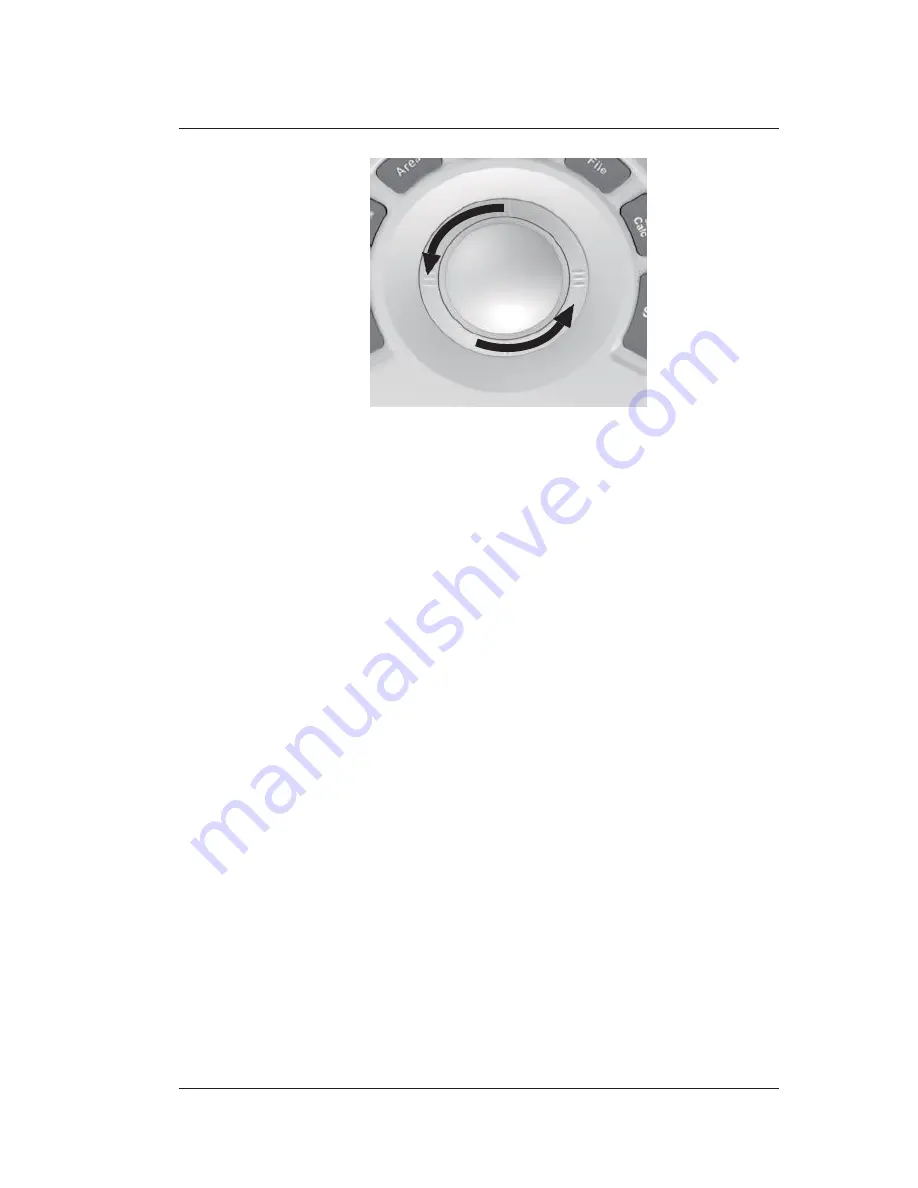
7.


Place the trackball and the ring back in the control panel, press the bulges in the ring 

with both hands and turn the ring clockwise to install the trackball. 


15

2  Maintenance Checks 

To maintain the safety and functionality of the system, the following maintenance checks 

must be performed by service personnel at least once every year. 


Electric Safety 

● 

Integrity of power cable 

● 

Protective conductor resistance 

● 

Ground line leakage current 

● 

Enclosure leakage current 

● 

Patient leakage current 

● 

Patient auxiliary leakage current 


15

2

3

2  Mechanical Safety 

● 

Appearance of the system enclosure 

● 

Appearance of the control panel and the key panel 


NOTE: 

The  surfaces  of  the  control  panel  or  the  key  panel  may  be  abrasive  because  of  the 

split  liquid  or  other  cleaning  sprays.  Check  the  potential  problems  carefully  when 

performing maintenance checks. 

● 

Control of foot brake 

Содержание P25 EXP

Страница 1: ...User Manual P25 EXP Ultrasound System Version 1 4...

Страница 2: ...nual The manufacturer does not assume any liability arising out of any infringements of patents or other rights of third parties This manual is based on the maximum configuration and therefore some co...

Страница 3: ...result in death or serious injury Indicates a potentially hazardous situation which if not avoided may result in malfunction or damage of the system NOTE Indicates precautions or recommendations that...

Страница 4: ...ture Limits 8 1 3 5 Imaging Functions that Change Acoustic Output 8 1 4 Safety Symbols 8 2 Overview 2 1 System Configuration 12 2 2 Physical Specifications 12 2 3 System Components 13 2 3 1 Peripheral...

Страница 5: ......

Страница 6: ...ecting the Video Printer 34 3 7 3 Connecting the Network Printer 34 3 7 4 Connecting the USB Printer 35 4 Customize 4 1 General System Settings 38 4 1 1 General Settings 38 4 1 2 Display Settings 40 4...

Страница 7: ...1 1 Beginning a New Patient 70 5 1 2 Retrieving Archived Information 72 5 1 3 Using DICOM Worklist 73 5 2 Pausing Resuming an Exam 73 5 2 1 Pausing an Exam 73 5 2 2 Resume an Exam 73 5 3 Completing Di...

Страница 8: ...DI CW 110 7 Elastography 7 1 Acquiring Elastography Images 112 7 2 Optimizing Elastography Images 113 7 2 1 Strain Map 114 7 2 2 Strain Process 115 7 2 3 Transparency 115 7 2 4 Contrast 115 7 2 5 Pers...

Страница 9: ...13 Customizing Presets 134 9 2 14 Performing Follicle Auto Measurement 134 10 4D image 10 1 Acquiring 4D Images 136 10 1 1 Entering the Real Time 4D Imaging 136 10 1 2 Acquiring Dynamic 3D Image 138...

Страница 10: ...n Image 153 12 3 Sharing Data 154 12 4 Backing up Data 154 12 4 1 Backing up Data to a USB drive 154 12 4 2 Backing up Data to DVD 154 12 5 Importing Data to the System 155 13 Working with DICOM 157 1...

Страница 11: ...ystem Maintenance 15 1 Cleaning the System 184 15 1 1 To clean the system surface 184 15 1 2 To clean the dust filter 184 15 1 3 To clean the trackball 184 15 2 Maintenance Checks 185 15 3 Troubleshoo...

Страница 12: ...Contents VIII Basic User Manual D 3 Disinfectant 200 AppendixEAcousticOutputData 201...

Страница 13: ...afety of both operator and patient please read the relevant details in this chapter carefully before using this system You should be thoroughly familiar with the precautions provided in this manual Ot...

Страница 14: ...attempting to use the ultrasound system Keep this manual with the system at all times Periodically review the procedures for operation and safety precautions 1 2 1 Electrical Safety Only qualified ph...

Страница 15: ...nto the system s surfaces as fluid seepage into the electrical circuitry may cause excessive electrical currenet leakage or system failure If any water is carelessly spilled onto the system immediatel...

Страница 16: ...Do not knock or shake the system Ensure that the casters are intact and can rotate well before moving the system Always use the handle to move the system Ensure the foot brakes are released and all c...

Страница 17: ...e use Prepare use store and dispose the cleaner disinfectant and sterilant according to the instructions provided by manufacturers Disconnect the probe from the system after freezing an image or power...

Страница 18: ...is required to practice ALARA when using ultrasound energy Practicing ALARA ensures that the total energy level is controlled below a low enough level at which bioeffects are not generated while diag...

Страница 19: ...t is actually occurring The MI should be used as a guide for implementing the ALARAprinciple Thermal Index TI The TI value informs the operator about the conditions that might lead to an increase in t...

Страница 20: ...erature the probe stops working automatically when its temperature reaches the limit The surface temperature of the probe is displayed on the right side of the screen 1 3 5 Imaging Functions that Chan...

Страница 21: ...anesthetics Type BF Applied Part Main switch OFF Main switch ON On Standby switch Footswitch Connector Protective earth ground Equipotentiality Alternating current Degree of IP protection Non ionizin...

Страница 22: ...tor Keep this way upward Serial Number Rechargeable for battery only This symbol indicates that waste electrical and electronic equipment must not be disposed of as unsorted municipal waste and must b...

Страница 23: ...adopts advanced ultrasonic Doppler technologies To ensure the performance and availability of this ultrasound system you should be thoroughly familiar with the operations of system components the cont...

Страница 24: ...figuration The standard system configuration mainly consists of the following items Main unit Probes Others See the Packing List in the packaging box 2 2 Physical Specifications System dimensions appr...

Страница 25: ...w of the System 1 LCD Monitor 9 Charging Discharging Indicator 2 Touch Screen 10 Battery Capacity Indicator 3 Coupling Gel Holder 11 Caster 4 Control Panel 12 Footswitch Port 5 Front Panel 13 Pencil P...

Страница 26: ...iew 14 Basic User Manual 17 18 24 23 19 20 22 21 Figure 2 2 Left View of the System 17 Speaker 21 Peripheral Device Panel 18 Fan 22 DVD Drive optional 19 Cable Hanger 23 USB Port 20 Dust Filter 24 On...

Страница 27: ...network 4 S VIDEO Port Used for connecting a video device to acquire S VIDEO signals such as monitor or projector 5 Audio Signal Output Used for connecting an audio device 6 Video Printer Port Used fo...

Страница 28: ...they are of the same name In such condition only the system operated with the touch screen is described in this manual Figure 2 4 Control Panel No Name Description 1 Power Rotate it to adjust the ult...

Страница 29: ...mages cine or volume data For details refer to Section 4 1 4 Defined Key Settings 12 Print Press it to trigger the network printer if the network printer is successfully connected 13 Video Print Press...

Страница 30: ...t to switch between measurement markers when performing the distance or ellipse measurement Press it to undo the trace when performing a trace measurement 25 Calc Press to activate the application spe...

Страница 31: ...Rotate it to adjust the angle of hip joint when performing the pediatrics measurement 32 Arrow Press it to add arrows on an image 33 Body Mark Press it to add body marks on an image 34 Depth Rotate i...

Страница 32: ...al Position 2 Institution Name 13 Clipboard 3 Patient ID 14 Network Connection Status 4 Probe Model Exam Type 15 Cine Loop Icon in frozen mode 5 Patient Name 16 Imagining Area 6 MI and TIS Indices 17...

Страница 33: ...eature to be performed To avoid damaging the touch screen Do not expose it in direct sunlight Tap it gently with fingers Do not operate it with a sharp or hard object Do not locate it in environmental...

Страница 34: ...lly rotating it clockwise can enable the feature or increase the value of the corresponding parameter rotating it anticlockwise can disable the feature or decrease the value of the corresponding param...

Страница 35: ...en Imaging Mode buttons Imaging Feature buttons Imaging Parameter buttons Figure 2 8 Imaging Mode Menu Annotation Menu The annotation menu as shown below is used to select an annotation or body mark P...

Страница 36: ...Subclav A Lt Vertebral A Lt CCA Lt Bulb Lt ICA Lt ECA Vessel Diam IMT Ant Vessel Area Sten D Sten A IMT Post Side Left Position Delete Last Figure 2 10 Measurement Menu Key Panel of Touch Screen The k...

Страница 37: ...the System System preparation is necessary performed before using the system The preparation includes but is not limited to moving positioning or adjusting the system connecting the probe and the peri...

Страница 38: ...6 Cable Trough 7 Fixing Bracket 8 Main Unit Perform the following steps to assemble the system 1 Take out the control panel back cover by removing two M3 8 screws with a cross screwdriver 2 Remove M4...

Страница 39: ...rechargeable lithium battery When the adapter is connected to the mains supply the battery is charged until it is full 3 3 1 Using the Mains Supply Two switches are provided for the system The power...

Страница 40: ...ly wash the area immediately with clean water If the fluid comes into contact with your eyes immediately flush your eyes with water and seek an oculist for help If the battery is found damaged severel...

Страница 41: ...he battery damage causing the system damage observe the following precautions Do not immerse the battery in water or allow it to get wet Do not discard the battery in a fire Do not leave the battery i...

Страница 42: ...ty of the system maintenance must be performed at least once every year For details refer to 15 System Maintenance 3 4 1 Powering On the System 1 Set the power switch on the rear panel to the position...

Страница 43: ...s from the lower arm To adjust the monitor horizontally swivel the upper arm left or right 3 5 2 Adjusting the Display Monitor To swivel the LCD monitor Grip the upper and lower sides of the monitor t...

Страница 44: ...enter the monitor menu Press Enter press or to highlight Auto Adjust and press Enter to automatically optimize the monitor settings Press to display the setting menu for Contrast Pressing can increas...

Страница 45: ...o the horizontal position and then pull the probe connector straight out vertically 3 7 Connecting the Peripheral Device 3 7 1 Connecting the Footswitch To avoid damaging the footswitch do not place t...

Страница 46: ...rinter to the system and turn on the printer The printer settings are displayed as below 2 Press OK on the control panel menu of the printer 3 Press or to select Network Config and then press OK to co...

Страница 47: ...Default Gatewayand DICOM AE Title NOTE IP address and Printer IP should be set in the same network segment 5 Set Default Printer to Net Printer and set the IP address of the printer 6 Click Add Print...

Страница 48: ...This page is intentionally left blank...

Страница 49: ...Setting menu allows you to specify general system settings printing measurement and calculation settings You can also define the annotation library and shortcut keys All your customized settings can...

Страница 50: ...nually type the value Select an option from each drop down list Select Save Exit to save any changes and exit the System Setting menu Select Exit to quit the System Setting menu 4 1 General System Set...

Страница 51: ...e system date and time Select this item to set the system date and time manually in the pop up text box NOTE You should set the system date and time for your initial use of the system Time Format Set...

Страница 52: ...l Auto Enable or disable the auto focus feature Set it to On the focal depth varies with the depth in the B mode The focal depth varies with the ROI position in the CFM PDI TDI mode Set it to Off the...

Страница 53: ...In Gallery View images and cines coming with the system or imported from external storage devices Show Images in Gallery Perform the following steps to perform a demonstration 1 Click Show Gallery to...

Страница 54: ...age format Choose from WMV or AVI Still Format Set the image storage format Choose from JPG BMP or TIF Store Frame Amount Set the maximum number of frames for cine The range is 100 1000 frames Print S...

Страница 55: ...ave the desired image Cine Tick it and press the P1 key to save the desired cine Volume Tick it and press the P1 key to save the desired volume data Print Tick it and press the Save or P1 key to save...

Страница 56: ...print server from the drop down list when defining the P1 key Activate new patient Tick it and the New Patient screen will automatically appear after you end the exam by pressing the End Exam key The...

Страница 57: ...amic IP or Static IP IP Address Set the IP address of the system NetMask Set the netmask address of the system Default Gateway Set the gateway address of the system Speed Duplex Click Advance Speed an...

Страница 58: ...etworks on the menu 2 Select the desired wireless network and click Connect 3 Input the password in the pop up dialogue box if needed and click OK Printer Settings Item Description Printer Driver The...

Страница 59: ...then click Delete to delete it from the library Click on an annotation in the Selected list and then click or to arrange its display System Setting Selected L L Lobe RK Hepatic A Pancreas R R Lobe LK...

Страница 60: ...down list beside Application of Available 3 Add desired bodymarks in the selected bodymark library to the Selected list Select a bodymark and then click to add it to the Selected list Click to add al...

Страница 61: ...ment Items Item Description BSA In accordance with the setting of this item the system calculates BSA value automatically after you enter the height and weight of the patient on the Patient Informatio...

Страница 62: ...the current result box when unfreezing the image Freeze on Measure Enable or disable the frozen feature after pressing the Calc or Caliper key in the real time mode Result Font Size Set the font size...

Страница 63: ...defined shortcut key Small Parts Measurement Settings Select SMP from the drop down list beside Application and set the coefficient of the thyroid volume formula Obstetrics Measurement Setting Set the...

Страница 64: ...e by EFW Set the formula to estimate GA by EFW If it is set to None the system will not estimate GA by EFW and no corresponding values are displayed on the measurement report EFW GP SD Set the formula...

Страница 65: ...viation 2SD 2SD 2SD Figure 4 11 GA Table Growth Table Measurement Unit Save Exit Meas w d Exit Author 2SD mm mm Mean mm Deviation 2SD 2SD 2SD Figure 4 12 Growth Table Meas mm 2SD w d Mean w d 2SD w d...

Страница 66: ...drop down list beside Application 2 Select the Caliper or Calc 3 Select an imaging mode in the List frame and click Collection or Measurement 4 Click Add to add the desired collection or measurement o...

Страница 67: ...eps as follows 1 Select an exam type from the drop down list beside Application 2 Select the Caliper or Calc 3 Select an imaging mode in the List frame and click the Collection or Measurement 4 Click...

Страница 68: ...n click in the Special Items list to delete the desired parameter 4 7 Report Settings General Logo 170 60Pixel bmp 1 1 Title Font Title 1 24 Title 2 20 Title 3 20 Context 12 Display Items For Report P...

Страница 69: ...p down list Title Set the font size of the headline Subtitle Set the font size of the subtitle Context Set the text font size Background Color Set the background color of the measurement report Text C...

Страница 70: ...eters information and click Add to add a new server Select any server from the drop down list and click Delete to delete the server Remote Host Name Enter the name of the DICOM storage server IP Addre...

Страница 71: ...Stored Tick this item and the system sends an image to the DICOM storage server every time the image is saved Send At End of Exam Tick this item and the system sends all saved images to the DICOM stor...

Страница 72: ...commitment storage server Connect Timeout sec Set the time limit for the network connection timeout Repeat Count Set the number of repeated atempts for connecting to the DICOM commitment storage serve...

Страница 73: ...er Select any server from the drop down list and click Delete to delete the server Remote Host Name Enter the name of the DICOM worklist server IP Address Set the IP address of the DICOM worklist serv...

Страница 74: ...Result Set the maximum number of patient records that can be sent to the system Click Echo to verify the connection between the system and the DICOM worklist after you input the settings for the Remot...

Страница 75: ...f the MPPS server Port Number Set the port number of the MPPS server Connect Timeout sec Set the time limit for the network connection timeout Repeat Count Set the number of repeated atempts for conne...

Страница 76: ...ICOM Settings Menu Print Service Tab Item Description Service List Select the DICOM print server Select Append from the drop down list beside Service List input the relevant parameters information and...

Страница 77: ...or WHITE Orientation Set the print orientation Choose from PORTPAIT or LANDSCAPE Color Set the color of the image Choose from Color or Gray Film Size Set the film size Choose from 8INx10IN 8 5INx11IN...

Страница 78: ...M print server after you input the settings for the Remote HostName IP address DICOM AE Title Port Number A summary displays if the connection is verified 4 9 Defining System Defaults You can define y...

Страница 79: ...em defaults Click Export Import to enter the following menu General Peripheral Comment Bodymark Measure Touch Screen Report DICOM Load Default About Ensure the USB drive is connected to the system bef...

Страница 80: ...trol panel or tap Touch Adjust to calibrate the touch screen For details refer to Section 4 11 Calibrating the Touch Screen Tap Version to view the version information about the touch screen If the US...

Страница 81: ...9 5 Preparing for an Exam You can start an exam without entering any patient information To avoid patient identification errors you should always verify the identification information with the patient...

Страница 82: ...ormation Patient ID Last Name M I First Name DOB MM DD YYYY Age Sex Unknown Accession Exam Information Description Chief Compliant Past History Referring M D Performing M D Sonographer Comments Y Auto...

Страница 83: ...ssion Enter manually the exam ID for the current patient special characters are prohibited to be entered Weight and Height Enter manually the weight and height for the current patient BSA The system w...

Страница 84: ...pleted the system will remind you to complete or discontinue the exam For details refer to Section 5 3 2 Discontinuing an Exam 5 1 2 Retrieving Archived Information You can retrieve the archived infor...

Страница 85: ...the control panel to select it 3 Exam the desired patient Click New Exam to start a new exam 5 1 3 Using DICOM Worklist You can acquire the patient information using the DICOM worklist if the system i...

Страница 86: ...enter the New Patient screen and then click Patient List to enter the Patient Exam List screen 2 Click New Patient to enter the New Patient screen Input the new patient information and click OK A dial...

Страница 87: ...75 6 Acquiring Images You can acquire images by optimizing the relevant parameters for clinical diagnosis...

Страница 88: ...screen NOTE Ensure the probe model and icon displayed on the application mode screen are consistent with the connected probe If a problem is found check that the probe is connected to the system firm...

Страница 89: ...tomized application preset If the name of the application preset exists you can click Replace Exam to replace it 6 1 2 To arrange the presets display Click Presets display to arrange the presets displ...

Страница 90: ...plication click Delete Yes to delete the application preset Click Restore Factory Default Yes in the pop up dialogue box to restore factory defaults 6 2 Acquiring B Mode Images B mode imaging is inten...

Страница 91: ...on 2 3 3 Basic Screen 6 2 2 Optimizing B Mode Images The touch screen displays all controls related to the B mode imaging as shown in the figure you can use them to optimize B mode images B PDI Pannor...

Страница 92: ...ontrol panel clockwise to increase the value Rotate the B knob on the control panel anticlockwise to decrease the value TGC TGC Time Gain Compensation is used to adjust the gain that allows compensati...

Страница 93: ...reen to decrease or increase the value Depth Depth is used to adjust the distance over which the B Mode image is anatomized To adjust the depth Rotate the Depth knob on the control panel clockwise to...

Страница 94: ...ry high resolution such as the thyroid or testicles A lower line density is useful when scanning fetal heart beat and adult cardiac applications To adjust the line density Tap the left part of Line De...

Страница 95: ...d array probes is used to adjust the frame rate You can adjust the sector width or angle to get more information without moving the probe The region of interest of the object can be adjusted after you...

Страница 96: ...to increase the value Image Rotation You can rotate the image to get more information Only transvaginal and transrectal exams are available for this feature To rotate the image Tap the left or right...

Страница 97: ...c beam NOTE Only the linear probes are capable of using the steer 6 3 Acquiring Color Flow Images Color Flow imaging adds the color coded qualitative information in the B Mode image Color Flow imaging...

Страница 98: ...e CFM mode image PDI uses the number and amplitude of red blood cells going through in the flow to create the color coded imaging A flow with slow velocity and small rate can be displayed in PDI There...

Страница 99: ...by using the phased array probes TDI Tissue Doppler Imaging is a color flow imaging technique which detects the low frequency signal reflected from the cardiac muscle TDI provides the flow information...

Страница 100: ...FRQ 2 2 Figure 6 8 TDI Mode Imaging Screen 3 Adjust color flow ROI Move the trackball to position color flow ROI Press the confirm key on the control panel to adjust the size of color flow ROI Press...

Страница 101: ...uch screen to turn the current menu to the previous or the next page if it displays over one page Or rotate the knob on the control panel that is directly below the selected item to adjust the value N...

Страница 102: ...o increase the value Line Density Line density refers to the amount of ultrasound beam that makes up the image Increasing the value of line density improves the resolution and decreases frame rate The...

Страница 103: ...ues for fast moving organs or tissues and higher persistence values for a smoother appearance To adjust the persistence Tap the left part of Persist on the touch screen to decrease the value Tap the r...

Страница 104: ...B Reject value suppresses more grayscale pixels To adjust B Reject Tap the left part of B Reject on the touch screen to decrease the value Tap the right part of B Reject on the touch screen to increas...

Страница 105: ...n the anatomy of interest and then learn about the tissue motion along that line in M mode trace In M mode y axis is used to display the position or depth of the tissue and x axis is the time scale 6...

Страница 106: ...ckball is idle for more than 0 5s 5 Optimize M mode image For details refer to Section 6 4 3 Optimizing M Mode Images 6 Press the M key again to exit the screen 6 4 2 Anatomical M Mode Anatomical M mo...

Страница 107: ...e Angle knob on the control panel to adjust the angle of M line 3 Press the Update key on the control panel to activate the anatomical M mode NOTE Once the anatomical M mode is activated you can move...

Страница 108: ...ctly below the selected item to adjust the value NOTE All parameters can be adjusted in a real time B mode Chroma and Display Format can also be adjusted in the frozen mode Gain M gain controls the ov...

Страница 109: ...adjust the setting Power Power is used to select the amount of ultrasound acoustic power produced by the probe The adjustment range of the power is 30 100 and 10 can be adjusted each time The real tim...

Страница 110: ...ing the anatomical site for PW Doppler examination The site where PW Doppler data is derived appears graphically on the B Mode image Perform the following steps to acquire PW mode images 1 Optimize a...

Страница 111: ...uency scale including positive and negative indicators Rotate the Audio knob on the control panel to adjust the audio volume NOTE Once the PW mode is activated you can move the trackball to stop the D...

Страница 112: ...n of the flow cursor 7 Press the PW key again to exit the screen 6 5 2 CW Mode Continuous Wave Doppler CW uses continuously transmitted and received ultrasound energy to generate a spectral display CW...

Страница 113: ...g the trackball to the left or the right 4 Rotate the Angle knob on the control panel to adjust the angle of the flow cursor 5 Press the Update key on the control panel to activate the CW mode The CW...

Страница 114: ...er the inactivated B CW mode 2 the following screen appears Figure 6 19 Inactivated B CW Mode 2 Imaging Screen You can also adjust the position and angle of spectral Doppler line and the direction of...

Страница 115: ...selected item to adjust the value NOTE You can adjust all parameters in the real time PW CW mode but can only adjust Baseline Chroma and Display Format in the frozen PW CW mode Gain PW CW gain is use...

Страница 116: ...PRF is automatically enabled when a certain value is reached NOTE The linear probes are not available for HPRF Baseline Baseline represents the position of zero velocity or frequency The velocity rang...

Страница 117: ...lect the amount of ultrasound acoustic power produced by the probe The adjustment range of the power is 30 100 and 10 can be adjusted each time The real time value of the power is displayed in the ima...

Страница 118: ...een to disable the feature and INVERT disappears from the display Video Invert Video invert is used to view the background of the spectral display from a different perspective To enable or disable the...

Страница 119: ...modes and can be applied to view the image The triplex mode includes B CFM TDI M B CFM PDI TDI PW and B CFM PDI CW 6 6 1 B CFM TDI M NOTE Only the phased array probes are available for B CFM TDI M Per...

Страница 120: ...exit the screen 6 6 2 B CFM PDI TDI PW Perform the following steps to acquire the image 1 Optimize a CFM PDI TDI mode image 2 Press the PW key on the control panel to enter the inactivated B CFM PDI...

Страница 121: ...f the flow cursor 5 Press the Update key on the control panel to activate the PW mode The PW spectrum is displayed at the lower part of the screen after being activated as shown Figure 6 24 Figure 6 2...

Страница 122: ...ctivated CFM PDI TDI PW Mode 2 Imaging Screen You can also adjust the position and angle of spectral Doppler line the size of the sample volume gate and the direction of the flow cursor 7 Press the PW...

Страница 123: ...surroundings Furthermore it provides an elastography image to discover tumors stiffer than the surrounding tissue The elastography image displays a range of map shades from the softest tissue in the...

Страница 124: ...on the right Tap or on the touch screen to enter the single or dual split screen display Strain Map Elastography image in ROI B Mode Image Strain Curve Figure 7 1 Elastography Imaging Screen Elastogra...

Страница 125: ...ative maximums on strain curves should be 0 5 1 If the absolute value is below 0 5 or over 1 the compression is too hard or too low for correct elastography results 5 Adjust the elastography ROI To ac...

Страница 126: ...is directly below the selected item to adjust the value NOTE All parameters can only be adjusted in real time elastography imaging 7 2 1 Strain Map Strains map allows you to select and apply a color...

Страница 127: ...ontrast enhances the color contrast for more accurate tissue stiffness information To adjust the contrast Tap the left part of Contrast on the touch screen to decrease the value Tap the right part of...

Страница 128: ...with Elastography Images You can work with the elastography images by using the features in the frozen mode such as cine review annotations data storage or measurement For details refer to Section 11...

Страница 129: ...ce difference between blood flow and tissue improve 2D imaging resolution for myocardial liver kidney and cephalic applications and enhance Doppler signals for blood flow Contrast imaging helps in obs...

Страница 130: ...ontrast imaging 1 Select C353 and Abdomen as the desired probe and exam type the system automatically enters the real time B mode 2 Position the target tissue in the B Color mode and observe the blood...

Страница 131: ...it displays over one page You can also tap Contrast or Tissue to make settings of the relevant tab To optimize the image by using controls in the following instructions Tap the left or right part of a...

Страница 132: ...ng steps to acquire contrast images 1 Inject contrast agents and tap Timer1 or Timer2 on the touch screen to start timing Once the timer is started Timer displays on the screen and the system starts t...

Страница 133: ...nalysis of the contrast agent intensity variation with duration Perform the following steps to make a TIC analysis 1 Tap TIC in the frozen mode to enter the TIC analysis screen 2 Position one or more...

Страница 134: ...B You can press the Clear key on the control panel to delete all ROIs and TIC curves 3 Analyze TIC curves for more information about circulation and perfusion Use the trackball to observe contrast ima...

Страница 135: ...of the anatomical structure 3D imaging can be performed by all probes but the quality of the images is closely related to 2D imaging 3D imaging mainly applies to obstetric exams and can be used to see...

Страница 136: ...ng a volume probe you can set the default inactivated 3D or 4D mode For details refer to Section 4 1 4 Defined Key Settings When using a non volume probe you should press the Freeze key and tap FreeHa...

Страница 137: ...9 Display the 3D imaging in the following instructions Tap or tap Start or press the Freeze key to display the 3D imaging in a full dual or quad display The system automatically enters the 3D imaging...

Страница 138: ...o turn the current menu to the previous or the next page Tap VolPre or press the Freeze key to return to the inactivated 3D mode Tap Exit on the 3D 4D tab to return to the real time B mode Tap Exit on...

Страница 139: ...s highlighted adjust the sample line by positioning the anchor with the trackball Only images inside the ROI are generated to a 3D image and the real time 3D image is also displayed when cropping revi...

Страница 140: ...observing dark areas vessels cysts X Ray displays all gray values within ROI It is suitable for observing tissue or tissue mass S Depth displays color signals of the echoes along the ultrasound beam I...

Страница 141: ...ng a box on the 3D image to remove irrelevant areas from interest area This feature is suitable for cropping regular reviews Perform the following steps to crop a review 1 Tap Edit or to enable the fe...

Страница 142: ...review can undo the last cut Taping can redo the last cut 9 2 6 Moving Rotating Magnifying Images To select an image Tap 3D 4D A B C or 3D to select the desired image To move images Tap View tap the l...

Страница 143: ...roma to choose the color scheme for reference images Tap M Slice tap the left right part of B Chroma to choose the color scheme for slices The grayscale or color map on the top right of the imaging ar...

Страница 144: ...image and then tap or to select the display formate 3 Move the cursor on the desired reference image by using the trackball and observe reference images on the screen 9 2 9 Observing Reviews by the S...

Страница 145: ...left or right Move the cursor on the one slice by using the trackball to select it To adjust the slice position slice distance slice number Tap the Left Right part of Adjust Pos to fine tune the sele...

Страница 146: ...y effective when entering 3D imaging from a frozen B mode image 9 2 12 Restoring the Image Tap 3D 4D Reset to restore the relevant settings 9 2 13 Customizing Presets You can modify parameters adjust...

Страница 147: ...4D imaging adds the dimension of movement to a 3D image by providing continuous real time displays of internal organs or fetus 3D imaging provides single frame images while 4D imaging provides contin...

Страница 148: ...image 5 Tap 3D 4D on the touch screen to enter the inactivated 4D mode by default NOTE When using a volume probe you can set the default inactivated 3D or 4D mode For details refer to Section 4 1 4 D...

Страница 149: ...ht part of Stability to enable or disable the image quality feature For other parameters refer to Section 9 2 Working with 3D Images 8 Display the 3D imaging in the following instructions Tap or tap S...

Страница 150: ...e or press the Freeze key to return to the inactivated 4D mode Tap Exit on the 3D 4D tab to return to the real time B mode Tap Exit on other tabs to switch to the 3D 4D tab 10 1 2 Acquiring Dynamic 3D...

Страница 151: ...139 11 Working with Images You can work with the acquired images by using the features provided by the system such as the split screen display panoramic display and annotations...

Страница 152: ...een Display 1 Press the B CFM M PW or CW key on the control panel to select an imaging mode for a real time scan 2 Press the Dual key on the control panel or tap on the touch screen to enter the dual...

Страница 153: ...CFM M PW or CW key on the control panel to select an imaging mode for a real time scan 2 Tap on the touch screen to enter the quad split screen display The B mode image is taken as an example in the f...

Страница 154: ...t resolution and improves border delineation THI is useful in difficult to image patients In real time scan of B mode tap THI on the touch screen to enable the THI mode and THI or PHI appears at the l...

Страница 155: ...maging Perform the following steps to apply panoramic imaging 1 Optimize the B mode image 2 Tap Panoramic on the touch screen to enter the inactivated Panoramic Imaging mode You can press the Freeze k...

Страница 156: ...Overview on the touch screen to restore the image to the default setting Make measurements annotations and body marks 7 Tap Exit on the touch screen to exit panoramic imaging Frozen Panoramic Imaging...

Страница 157: ...an image 1 Press the Zoom key on the control panel to enable this feature A size multiplier is displayed in the information area of the basic screen a thumbnail is displayed in the lower left corner o...

Страница 158: ...Auto Play to play the cine review automatically Tap Auto Play again to stop the cine review Or tap the left or right part of Cine Speed to adjust the review speed during the cine review 11 4 2 Cuttin...

Страница 159: ...r tap Exit on the touch screen to exit Annotating an Image with Arrows Perform the following steps 1 Press the Arrow key on the control panel and the cursor becomes an arrow 2 Position the arrow to th...

Страница 160: ...e touch screen NOTE You can enable the annotation cleared feature For details refer to Section 4 1 1 General Settings To delete body marks Perform the following steps 1 Press the Body Mark key to ente...

Страница 161: ...e parts including earth grounding Power off the system if the patient is found to use a pacemaker or implantable cardioverter defibrillators because the system may interfere with these devices 11 6 1...

Страница 162: ...isable the waveform inversion function R Trigger Enable or disable the R trigger function When enabled the R Trigger menu pops up the menu contains Trigger Delay Frame Count and Frame Int NOTE In orde...

Страница 163: ...ges Data Images in this ultrasound system include frame images and cine you can save or review them after the acquisition Meanwhile images can be also backed up to a USB drive or a DVD for future revi...

Страница 164: ...Image 1 Press the Save key on the control panel in the 3D 4D mode 2 Select Image in the pop up dialogue box to save the current image Or select Volume in the pop up dialogue box to save the volume dat...

Страница 165: ...DICOM Print Print If the patient has had more than one exam you can select the desired exam from the Exam drop down list 2 Move the trackball to the thumbnails and select the confirm key to choose one...

Страница 166: ...ing steps 1 Connect a USB drive to the system 2 Choose the Patient key Patient List Patient Review to enter the Patient Review screen 3 Select USB from the Import Export drop down list 4 Click Export...

Страница 167: ...ew Image screen 12 5 Importing Data to the System NOTE Only data generated by this ultrasound system can be imported Ensure the current exam is completed before you import data Otherwise you may have...

Страница 168: ...This page is intentionally left blank...

Страница 169: ...gurated with the DICOM module you can Search the archived patient information set on the DICOM server and copy the patient information to the system so that the correct patient can be examined Send st...

Страница 170: ...n the General Settings menu Key Configuration tab 3 Press the Save key or the P1 key in the real time or frozen mode to send the current image to the DICOM storage server If the transmission fails a p...

Страница 171: ...and then click View to enter the Exam Review screen 3 Select the desired exam 4 Click DICOM Print to send the patient information and the relevant images to DICOM print server If you only want to send...

Страница 172: ...ar all the search information Clicking Date Time can display the patient data by order of oldest or newest input date time 2 Start an exam a Select the desired patient b Click Select to start an exam...

Страница 173: ...ly be added when you perform the scan or other order operations Perform the following steps 1 Choose the Patient key Patient List Patient Review to enter the Patient Review screen 2 Click PPS Screen t...

Страница 174: ...d to confirm whether the images or structured reports are successfully stored to the DICOM storage server If you want to check the status of items sent to the DICOM storage server choose the Patient k...

Страница 175: ...mation Select the desired patient information and click Refresh to refresh the patient information If it does not work you can click Resend to resend the information Click All Select Resend Fail to re...

Страница 176: ...This page is intentionally left blank...

Страница 177: ...should become thoroughly familiar with the operations of the probe and biopsy bracket before using them To ensure the performance of the probe and the biopsy bracket you should periodically check clea...

Страница 178: ...ransducer Orientation mark Junction line Handle Handle Junction line Transducer Body surface probe Endocavitary probe Intraoperative probe 14 1 1 Available Probes The available probes are listed as fo...

Страница 179: ...l in accordance with the relevant local regulations Read and understand all precautions in the relevant manual of the coupling gel before use For recommended coupling gels please refer to Appendix D 1...

Страница 180: ...Hold the probe and unroll the sheath onto the probe d Pull the probe sheath tightly over the face of the probe to remove wrinkles e Secure the sheath to the probe with the adhesive tapes or elastic ba...

Страница 181: ...probe may be damaged You should clean the probe before and after each use Probe cleaning is an essential step of the disinfection and sterilization Perform the following steps to clean the probe 1 Rem...

Страница 182: ...infect the entracavitary probe and clean and sterilze the probe for biopsy and coming into contact blood after exam Do not use an expired disinfectant sterilant Store the probe in a sterile environmen...

Страница 183: ...ch use Perform the following steps 1 Clean the probe For details refer to Section 14 1 3 Cleaning the Probe 2 Perform the medium level disinfection to the surface probe as shown in Table 14 1 until th...

Страница 184: ...able 14 2 Recommended Method for High level Disinfection Disinfectant Manufacturer Active Ingredients Level for Active Ingredient Contact Type Contact Period Cidex Activated Dialdehyde Solution J J Gl...

Страница 185: ...cable damages Disinfection Perform the following steps to disinfect the probe cable 1 Use a lint free soft cloth dampened with mild soapy water to wipe the probecable 2 Rinse the cable with fresh runn...

Страница 186: ...or sterilize the probe before storing it or store it in a disposable probe package Do not expose it to direct sunlight or sudden environmental temperature changes Store the probe alone to avoid any i...

Страница 187: ...needle must be displayed within the guidelines Contact the manufacturer or the local distributer if the needle path is not accurately indicated Do not freeze an image when performing a biopsy To avoi...

Страница 188: ...ody surface NGB18L A 18L A 14G 16G 18G 20G 22G Body surface NGB9L A 9L A 14G 16G 18G 20G 22G Body surface NGB13L A 13L A 14G 16G 18G 20G 22G Body surface NGB3C B 3C B 14G 16G 18G 20G 22G Body surface...

Страница 189: ...r sterile gloves 3 Unfold the probe sheath and apply an appropriate amount of coupling gel to the inside of the sheath and onto the face of the probe 4 Hold the probe and unroll the sheath onto the pr...

Страница 190: ...on loose or missing some parts on the biopsy bracket before the assembly 2 Wear sterile gloves 3 Unfold the probe sheath and apply an appropriate amount of coupling gel to the inside of the sheath 4 H...

Страница 191: ...d after using a rectal or transvaginal probe to perform a biopsy you should clean and sterilize the probe and all the biopsy accessories Otherwise it may cause a infection risk to the next patient who...

Страница 192: ...Biopsy to enable the biopsy feature For C322 C353 3P1 or L742 probe you can preset the biopsy angle 3 Perform a scan to locate the target 4 Perform the puncture by sliding the needle through the groov...

Страница 193: ...the biopsy enhanced region line The more closely to 90 of angle a the stronger brightness of the biopsy needle Tap Dual Live to enter the dual split display for better observation 6 Gently remove the...

Страница 194: ...y ethylene oxide Do not allow any sterilant to be air dried on the biopsy bracket Perform the following steps 1 Clean the biopsy bracket For details refer to Section 14 2 6 Cleaning the Biopsy Bracket...

Страница 195: ...183 15 System Maintenance To maintain the safety and functionality of the system periodically perform the maintenance for the system and accessories...

Страница 196: ...oard and the main unit Take special care and avoid to scratch the screens 4 Use a cotton swab to remove solids from between keys and controls 5 In case of blood or any infectious fluids or materials u...

Страница 197: ...maintain the safety and functionality of the system the following maintenance checks must be performed by service personnel at least once every year Electric Safety Integrity of power cable Protective...

Страница 198: ...rameters correctly For details refer to Chapter 6 Acquiring Images A4 The measurement cannot be performed after pressing the Calc key on the control panel Q4 Ensure you pressing the Calc key in the fr...

Страница 199: ...r the detailed disposal information consult the manufacturer or the local distributor The manufacturer is not responsible for any system content or accessories that have been discarded improperly 15 6...

Страница 200: ...This page is intentionally left blank...

Страница 201: ...agnetic compatibility Requirements and tests Classifications Type of protection against electrical shock Class I Degree of protection against electrical shock Type BF applied part Installation Type Mo...

Страница 202: ...190 Basic User Manual Appendix A Specifications Fuse Type 50CT Breaking capacity 1500 amperes at 250V AC Blowing time rating 30 minutes Max Current rating 3 15A Applied Parts Probes ECG electrodes...

Страница 203: ...ns CISPR 11 Group 1 The equipment uses RF energy only for its internal function Therefore its RF emissions are very low and are not likely to cause any interference in nearby electronic equipment RF e...

Страница 204: ...ines 2 kV for power supply lines 1 kV for input output lines Mains power quality should be that of a typical commercial or hospital environment Surge IEC 61000 4 5 1 kV line to line 2 kV line to earth...

Страница 205: ...P o w e r frequency 50 60Hz magnetic field IEC 61000 4 8 3 A m 3 A m Power frequency magnetic fields should be at levels characteristic of a typical location in a typical commercial or hospital enviro...

Страница 206: ...icable to the frequency of the transmitter Recommended separation distance 80MHz 800 MHz 80 MHz 2 5GHz Where P is the maximum output power rating of the transmitter in watts W according to the transmi...

Страница 207: ...sess the electromagnetic environment due to fixed RF transmitters an electromagnetic site survey should be considered If the measured field strength in the location in which the EQUIPMENT is used exce...

Страница 208: ...Rated Maximum Output Power of Transmitter W Separation distance according to frequency of transmitter m 150 kHz to 80 MHz 80 MHz to 800 MHz 800 MHz to 2 5 GHz 0 01 0 12 0 12 0 23 0 1 0 38 0 38 0 73 1...

Страница 209: ...0 23alf where In Situ In Situ Intensity Value Water Water Value Intensity e 2 7183 a Attenuation Factor Tissue a dB cm MHz Amniotic Fluid 0 006 Brain 0 53 Heart 0 66 Kidney 0 79 Liver 0 43 Muscle 0 5...

Страница 210: ...can be used with this system For details refer to Section 14 1 1 Available Probes D 1 Coupling Gel Probe Model Applicable Inapplicable MPTEE Mini 7 4 MPTEE 7 4 MPTEE MPTEE mini 12C ER Aquasonic 100 Aq...

Страница 211: ...E 7 4 MPTEE MPTEE mini 12C ER Mild soapy water T spray T spray II Transeptic 70 IPA LAP7 C9 5 10I2 6CI A 6CT A 7LI4 10I3 10L I 12L I 12LI A 12LT A 11L I T spray T spray II mild soapy water Transeptic...

Страница 212: ...5 BCL10 5 6V A 6V1A 6V2A 6V3A 6V7 8V A 6CT4 Cidex OPA Solution Cidex Metricide 14 Resert XL HLD Metricide 28 Metricide 30 VC6 2 VC8 3 VC311 VE9 5 VL12 5 CWD2 0 CWD4 0 CWD5 0 CWD8 0 PWD2 0 Cidex OPA So...

Страница 213: ...201 Appendix E Acoustic Output Data Please consult the accompanying CD...

Страница 214: ...P N 4710 01421X01 4710 00447A06 MEDISONO LLC 3511 Silverside RD Wilmington DE 19810 USA Email info medisono com 305 406 3931 Fax 305 406 2144...

Отзывы: