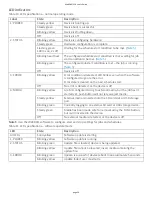
Safety voltages
Connect only voltages that are within the limits specified in this table.
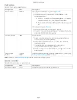
Table 17. Safety specifica ons
Parameter
Condi ons
Specifica on
Between any two
terminals
±30 V max
Channel-to-
channel isola on
None
Channel-to-earth
ground isola on
Con nuous
250 Vrms, Measurement Category II (
)
Withstand
2300 Vrms, verified by a 5 second dielectric withstand test
Note 9. Measurement Category II is for measurements performed on circuits directly connected to the
electrical distribu on system. This category refers to local-level electrical distribu on, such as that provided by
a standard wall outlet, for example 115 V for US or 230 V for Europe.
Cau on! Do not connect the device to signals or use for measurements within Measurement Categories
III or IV.
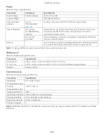
Signal connectors
Table 18. Screw terminal specifica ons
Parameter
Specifica on
Connector types
36-posi on spring terminal for thermocouple connec ons
6-posi on screw terminal for digital connec ons
Screw terminal
wiring
14 to 30 AWG copper conductor wire with 5 to 6 mm (0.20 to 0.24 in.) of insula on
stripped from the end
Spring terminal
wiring
16 to 28 AWG copper conductor wire with 7 mm (0.28 in.) of insula on stripped from
the end
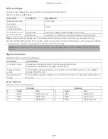
Screw terminal
Table 19. Screw terminal pinout
Terminal
Terminal
#
Label
Use
#
Label
Use
1
GND
Digital ground
4
DIO2
Digital bit 2
2
DIO0
Digital bit 0
5
DIO3
Digital bit 3
3
DIO1
Digital bit 1
6
GND
Digital ground
WebDAQ 316 User's Guide
page 29


