IM 812 / Page 19 of 24
such as kinks, cuts, abrasions and signs of malfunc-
tion, such as melting, pitting, discoloration or miss-
ing wires. Do not operate a unit with such signs until
it has been professionally inspected and repaired.
6.
Unplug the control pad and remove it before cleaning
the chassis. Clean the coils, fan blades, motors, ven-
tilation door screen, indoor and outdoor drain pans,
compressor and condensate drain (Styrofoam
®
open-
ing under ventilation damper door). Normal cleaning
can be accomplished by wiping the unit surface with
a damp cloth.
Cleaning compounds can cause damage to the packaged
terminal unit. Do not spray cleaning compounds onto the
discharge grille, return air opening, or unit controls. When
using cleaning compounds on carpets, floors or walls,
turn the unit off to avoid drawing vapors into it. Avoid coil
cleaners that include Lithium Hydroxide, Sodium Hydrox-
ide, Potassium Hydroxide Magnesium Hydroxide, Ammo-
nium Hydroxide, Sulfuric Acid, Hydrochloric Acid, Phos-
phoric Acid, Hydrofluoric Acid, Acetic Acid, Chromic Acid,
or any derivative of the above as they will damage the
coil coating.
7.
Dry equipment thoroughly, especially electric parts.
8.
Clean any rust spots with steel wool and coat with
rust-inhibiting paint.
9.
Clean insulation or replace if necessary.
10. Check insulation on refrigerant tubing and replace if
necessary.
11. Check all fasteners and tighten as required.
12. Clean ventilation door screen and oil linkage.
13. Reinstall the control pad and test run the chassis to
check for rattles, etc., before replacing it in the wall
sleeve.
Scheduled Maintenance
This unit is built to last. With proper care, the unit can provide
uninterrupted service for many years. Scheduled maintenance
of this equipment as described below, is the key to the
equipment’s longevity.
A. Air filters must be cleaned at regular intervals. Twice an-
nually may be adequate in some areas, while twice monthly
may be required in others. Areas with high dirt and lint
content or heavy usage of units require more frequent fil-
ter maintenance than those areas of relatively clean oper-
ating or low usage conditions. Unit malfunction will occur
if air filters are not kept clean. To remove the air filters,
grasp the top of the filters and pull straight up. Vacuum
the filters from the dirty side or wash with hot water and a
mild detergent. Allow the filters to dry thoroughly before
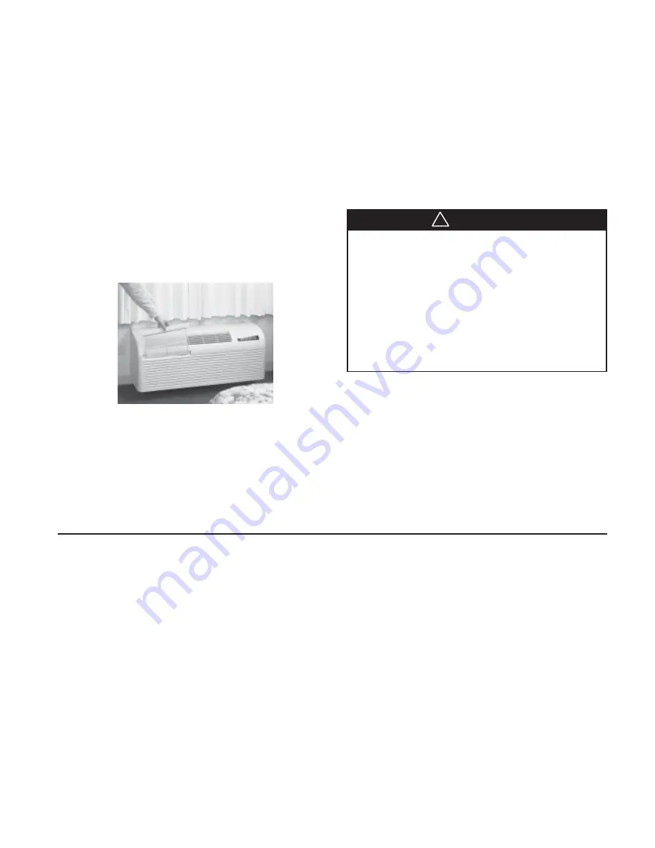
replacing them. See Figure 19.
B. Every year the chassis should be removed for a thorough
checkup. This should be completed as follows:
1.
Unplug unit from power source.
2.
Remove the front panel and clean it.
3.
Remove the chassis from the wall sleeve and move it to
the maintenance department. Replace it with spare chas-
sis or weather plate.
4.
Check all seals and insulation and repair as required.
5.
Check all wiring and controls for hazardous conditions,
Figure 19. Room Air Filters
WARNING
!
An inherent advantage of the PTAC/PTHP system is that shut-
down of one unit does not interrupt the operation of the rest
of the system. A further advantage is that a unit or part can be
quickly and easily replaced, thus minimizing the inoperative
time of the equipment. This is so, however, only if a replace-
ment unit or part is quickly available. In order to replace a part
quickly and keep all units in good operating condition, a small
stock of parts should be purchased along with the PTAC/PTHP
units. Where an owner carries such a stock, immediate re-
placement of a part is possible. The replaced part can then be
returned to the factory or one of its authorized service sta-
tions. So long as it is still in warranty, it is repaired or replaced
and returned to the owner without cost for shop labor and
material. Thus, the stock of replacement parts is constantly
replenished. Listed are the parts which we recommend be
carried in stock, together with the quantity per 50 condition-
ers installed.
Recommended Spare Parts
Cooling Chassis ................................................................... 1
Compressor Overload Device .............................................. 1
Compressor Running Capacitor .......................................... 1
Indoor Fan Motor ................................................................. 1
Indoor Fan Wheel ................................................................. 1
Indoor Fan Motor Capacitor ................................................ 1
Outdoor Fan Motor .............................................................. 1
Outdoor Fan Blade ............................................................... 1
Outdoor Fan Motor Capacitor ............................................. 1
Control Pad* ......................................................................... 1
Control Box Internal PC Board ............................................ 1
Control Box External PC Board with Dip Switches............... 1
Universal Electric Heater ...................................................... 1
For parts or service, contact your local distributor or call
1-800-377-2787, or 763-553-5009.
*Remote thermostats should be stocked if they are being used
in lieu of the control pad.


