background image

28


AGZ 010B through 034B 

IOMM AGZB1 


Dimensions & Weights  

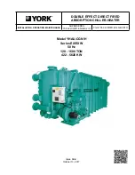
Figure 8, AGZ 010BS - 017BS, Packaged (See page 30 for additional dimensions and weights) 


Figure 9, AGZ 020BS - 034BS,packeged (See page 30 for additional dimensions and weights) 


.875

CONTROL

ELECTRICAL

KNOCKOUT

R331987001 00 CERTIFIED, 2 FAN, AGZ-B

21.18

46.18

X

24.57

5.17

73.80

4.00
MOUNTING HOLES
DIA. 1.00 INCH
QTY. 4

49.06

2.61

40.18

.875

POWER ENTRY

KNOCKOUT

(OTHER SIDE)

L1, L2

L3, L4

51.00

Y

Z

31.15

MOUNTING

HOLES

7.64

46.42

ACCESS

DOOR

CONTROL BOX

ACCESS DOORS

POWER

ENTRY

31.70

11.27

14.66

3.00

QTY.2

ACCESS

PANEL

EVAP.

INLET

EVAP.

OUTLET


DIM. A = AGZ020-025 = 24.6"

AGZ029-034 = 33.0"

DIM. B = AGZ020-025 = 40.2"

AGZ029-034 = 48.7"

NOTE:

L2 & L4 ARE LOCATED ON

1.

OPPOSITE SIDE OF UNIT.

ALL WEIGHTS ARE IN POUNDS.

2.

R331987101 CERTIFIED, 3 FAN, AGZ-B

84.95

21.18

X

106.23

49.06

49.06

5.17

B

A

2.67

.875

POWER ENTRY

KNOCKOUT

(OTHER SIDE)

L1, L2

L3, L4

AGZ020-025 =51

AGZ029-034 = 59

Y

Z

7.64

31.10

MOUNTING

HOLES

46.38

CONTROL PANEL

ACCESS DOORS

ACCESS

DOOR

POWER

ENTRY

11.27

31.70

3.00

QTY.2

14.66

ACCESS

PANEL

EVAP.

OUTLET

EVAP.

INLET

.875

CONTROL

ELECTRICAL

KNOCKOUT


Содержание AGZ 010BM

Страница 1: ...Chiller Part Number 331975001 Effective October 2007 Supersedes New Air Cooled Scroll Compressor Water Chillers AGZ 010BS AGZ 034BS Packaged Chiller AGZ 010BM AGZ 034BM Remote Evaporator 10 to 34 Tons...

Страница 2: ...Control Functions and Definitions 39 Unit Enable 41 Unit Mode 41 Power Up Start Delay 42 Ice Mode Start Delay 42 Unit State 42 Evaporator Water Pump State Control 43 Condenser Fans 44 Low OAT Start 44...

Страница 3: ...k all items carefully against the bill of lading Inspect all units for damage upon arrival Report shipping damage and file a claim with the carrier Check the unit nameplate before unloading to be sure...

Страница 4: ...ical Data Tables on pages 16 and 17 It is recommended that the unit be raised a few inches with a suitable support located at least under the mounting locations to allow water to drain from under the...

Страница 5: ...st applications When additional sound reduction is necessary locate the unit away from sound sensitive areas Avoid locations beneath windows or between structures where normal operating sounds may be...

Страница 6: ...3 Red RP 3 Red 350014858 020 025 029 034 RP 3 Green RP 3 Green RP 3 Red RP 3 Red 350014857 Spring AGZ Model RF LF RB LB Kit P N 010 CP 1 24 Brown CP 1 24 Brown CP 1 24 Brown CP 1 24 Brown 350014832 01...

Страница 7: ...ly to the evaporator heating cable mark the disconnect clearly so the disconnect is not accidentally shut off during cold seasons Failure to do so can cause a failure of the evaporator 8 The brazed pl...

Страница 8: ...vely slowly we recommend a minimum system volume of three to four times the flow rate GPM For example if the design chiller flow rate is 120 GPM we recommend a minimum system volume of 360 to 480 gall...

Страница 9: ...0 50 0 122 0 235 0 360 0 400 0 Max Adjst No Flow Lpm 2 8 4 1 6 1 7 3 11 4 27 7 53 4 81 8 90 8 NOTES 1 A segmented 3 inch paddle 1 2 and 3 inches is furnished mounted plus a 6 inch paddle loose 2 Flow...

Страница 10: ...ator The type storage disposal and handling of glycol used must be consistent with local codes Evaporator Water Flow and Pressure Drop Evaporator flow rate must fall between the minimum and maximum va...

Страница 11: ...del gpm L s ft kPa gpm L s ft kPa gpm L s ft kPa 010 15 0 0 9 2 4 7 1 24 0 1 5 5 8 17 3 40 0 2 5 15 2 45 5 013 19 5 1 2 1 5 4 5 31 2 2 0 3 7 11 0 52 0 3 3 9 6 28 9 017 24 0 1 5 1 7 5 0 38 4 2 4 4 1 12...

Страница 12: ...nt at the point of measurement no liquid Use the temperature reading the pressure reading and the Saturated P T Chart If the pressure is measured at 78 psig the chart shows the saturated vapor tempera...

Страница 13: ...103 9 44 14 7 26 4 210 96 2 105 4 46 16 4 28 1 215 97 7 107 0 48 18 1 29 7 220 99 3 108 4 50 19 7 31 3 225 100 8 109 9 52 21 3 32 9 230 102 3 111 4 54 22 9 34 4 235 103 8 112 8 56 24 4 35 9 240 105 3...

Страница 14: ...e visible in the oil sight glass 6 Check voltage of the unit power supply and make certain voltage is within 10 of nameplate rating Check unit power supply wiring for proper ampacity and a minimum ins...

Страница 15: ...osed the unit will start The controller will operate the unit in response to the leaving chiller water temperature or reset signals that may be present Equipment Protection Alarms The following condit...

Страница 16: ...APACITY REDUCTION STEPS PERCENT OF COMPRESSOR DSPLACEMENT Standard Staging 0 50 100 0 50 100 0 50 100 CONDENSERS HIGH EFFICIENCY FIN AND TUBE TYPE WITH INTEGRAL SUBCOOLING Coil Face Area One of Two Si...

Страница 17: ...RCENT OF COMPRESSOR DISPLACEMENT Standard Staging 0 50 100 0 50 100 0 50 100 0 50 100 CONDENSERS HIGH EFFICIENCY FIN AND TUBE TYPE WITH INTEGRAL SUBCOOLING Coil Face Area One of Two Sides Sq Ft M2 49...

Страница 18: ...Coil Face Area One of Two Sides Sq Ft M2 30 3 2 8 30 3 2 8 30 3 2 8 Finned Height x Finned Length In 84 x 52 84 x 52 84 x 52 Finned Height x Finned Length mm 2134 x 1321 2134 x 1321 2134 x 1321 Fins P...

Страница 19: ...ides Sq Ft M2 49 0 4 6 49 0 4 6 58 3 5 4 58 3 5 4 Finned Height x Finned Length In 84 x 84 84 x 84 100 x 84 100 x 84 Finned Height x Finned Length mm 2134 x 2134 2134 x 2134 2545 x 2134 2545 x 2134 Fi...

Страница 20: ...acity MCA Quantity Wire Gauge 75C Quantity Nominal Size In mm Recommended Maximum 208 56 3 6 AWG 1 1 00 25 70 70 230 54 3 6 AWG 1 1 00 25 60 70 460 26 3 10 AWG 1 1 00 25 30 30 010B 575 22 3 10 AWG 1 1...

Страница 21: ...8 31 2 31 2 5 8 2 21 4 225 225 230 30 1 30 1 5 8 2 23 7 225 225 460 15 5 15 5 2 8 2 10 7 114 114 017B 575 12 1 12 1 2 5 2 11 0 80 80 208 42 3 42 3 5 8 3 21 4 245 245 230 42 3 42 3 5 8 3 23 7 245 245 4...

Страница 22: ...AWG 350 kcmil 230 175 14 AWG 2 0 125 3 AWG 3 0 175 6 AWG 350 kcmil 460 175 14 AWG 2 0 60 14 AWG 1 AWG 80 10 AWG 1 0 020B 575 175 14 AWG 2 0 60 14 AWG 1 AWG 70 10 AWG 1 0 208 175 14 AWG 2 0 225 2 AWG 4...

Страница 23: ...208 82 3 4 AWG 1 1 00 25 110 110 230 80 3 4 AWG 1 1 00 25 90 100 460 41 3 8 AWG 1 1 00 25 50 50 017B 575 33 3 10 AWG 1 1 00 25 40 40 208 113 3 2 AWG 1 1 25 32 125 150 230 113 3 2 AWG 1 1 25 32 125 150...

Страница 24: ...2 31 2 5 8 2 21 4 225 225 230 30 1 30 1 5 8 2 23 7 225 225 460 15 5 15 5 2 8 2 10 7 114 114 017B 575 12 1 12 1 2 5 2 11 0 80 80 208 42 3 42 3 5 8 3 21 4 245 245 230 42 3 42 3 5 8 3 23 7 245 245 460 1...

Страница 25: ...AWG 350 kcmil 230 175 14 AWG 2 0 125 3 AWG 3 0 175 6 AWG 350 kcmil 460 175 14 AWG 2 0 60 14 AWG 1 AWG 80 10 AWG 1 0 020B 575 175 14 AWG 2 0 60 14 AWG 1 AWG 70 10 AWG 1 0 208 175 14 AWG 2 0 225 2 AWG...

Страница 26: ...e circuit 7 The recommended power lead wire sizes are based on an ambient temperature of 86 F 30 C Ampacity correction factors must be applied for other ambient temperatures Refer to the National Elec...

Страница 27: ...ER POWER FIELD WIRED MJ MJ IF SEPARATE EVAPORATOR HEATER POWER OPTION IS USED REMOVE MECHANICAL JUMPER BETWEEN TB1 5 AND TB1 6 TB1 15 AND TB1 16 17 12 N 120 VAC CHW PUMP RELAY BY OTHERS 120 VAC 1 0 AM...

Страница 28: ...1 15 MOUNTING HOLES 7 64 46 42 ACCESS DOOR CONTROL BOX ACCESS DOORS POWER ENTRY 31 70 11 27 14 66 3 00 QTY 2 ACCESS PANEL EVAP INLET EVAP OUTLET DIM A AGZ020 025 24 6 AGZ029 034 33 0 DIM B AGZ020 025...

Страница 29: ...4 HOT GAS BYPASS SUCTION LIQUID 51 00 Z Y 31 15 MOUNTING HOLES 7 64 46 42 ACCESS DOOR CONTROL BOX ACCESS DOORS POWER ENTRY ACCESS PANEL 875 CONTROL ELECTRICAL KNOCKOUT DIM A ACZ025 028 24 6 ACZ033 039...

Страница 30: ...on Liquid Temp Sensor AGZ Model Liquid Line Conn Brazed in L Suction Line Conn Brazed in S Temp Sensor NPT in TS Victaulic Water Conn In W Dimension A in mm 010 1 125 2 125 0 75 2 0 3 6 91 013 1 125 2...

Страница 31: ...253 2 779 761 369 361 Table 15 Remote Evaporator Dimensions and Weights CENTER OF GRAVITY IN LIFTING CORNER WEIGHTS LBS CONNECTION SIZES IN O D AGZ REMOTE EVAP X Y Z SHIP WT LBS OPN WT LBS L1 L2 L3 L4...

Страница 32: ...narily required except the occasional removal of dirt and debris from the outside surface of the fins Use locally purchased foaming condenser coil cleaners for periodic cleaning of the coil Condenser...

Страница 33: ...quipment Protection Alarms 37 Control Functions and Definitions 39 Limit Alarms 39 Control Functions 39 Unit Enable 41 Unit Mode Selection 41 Unit State 42 Evaporator Pump state 43 Condenser Fans 44 C...

Страница 34: ...s Staging The two scroll compressors are staged on and off as a function of leaving chilled water temperature Lead lag is automatic and switched every ten starts General Description Compressor Motor P...

Страница 35: ...ction 0 VAC Fault 24 VAC No Fault 5 Ice Mode Switch 0 VAC Normal 24 VAC Ice 6 Phase Voltage Fault 0 VAC Fault 24 VAC No Fault 7 Open 8 Open Digital Outputs Description Load Output OFF Output ON 1 Alar...

Страница 36: ...ge Down Delay 30 10 to 60 sec M Timers Evap Flow Proof 3 sec 1 to 10 sec M Evap Recirculate Timer 30 sec 15 to 300 sec M Low Evap Pressure Delay 30 sec 15 sec to 30sec M Ice Time Delay 12 hrs 1 to 23...

Страница 37: ...or Leaving Water Temperature Mode Range Unit Mode Cool 40 to 60 F Unit Mode Cool w Glycol 20 to 60 F Evaporator Freeze Temperature Mode Range Unit Mode Cool 36 to 42 F Unit Mode Cool w Glycol Ice w Gl...

Страница 38: ...larm to occur and states the action taken because of the alarm Otherwise the alarm is manually reset requiring the operator to clear the alarm Table 20 Shutdown Alarms Description Occurs When Action T...

Страница 39: ...p relative to the LWT setpoint to keep the lower end of the control band at least at 39 F If the band doesn t need to be shifted to achieve this it will remain centered on the active LWT setpoint In t...

Страница 40: ...sures for each circuit The pressure will be fitted to a curve made up of 13 straight line segments The points used to define these segments are as follows Pressure PSI Temperature o F 24 0 0 34 7 12 0...

Страница 41: ...col and TEST This setpoint can be altered by the keypad BAS and Mode input Changes to the Unit Mode Setpoint are controlled by two additional setpoints Available Modes Setpoint Determines the operatio...

Страница 42: ...n the first compressor starts while the unit is in ice mode While this timer is active the chiller cannot restart in Ice mode The time delay is user adjustable The ice delay timer may be manually clea...

Страница 43: ...3 T2 Power On Unit State Diagram Evaporator Water Pump State Control Operation of the evaporator pump is controlled by the state transition diagram shown below Figure 14 Evaporator Pump State Power ON...

Страница 44: ...r time than normal as well as multiple start attempts A low OAT start is initiated if the condenser saturated temperature is less than 85 F when the compressor starts Once this happens the circuit is...

Страница 45: ...lldown Rate setpoint when the unit mode is Cool If the rate exceeds this setpoint no more compressors can be started until the Pulldown Rate is less than the setpoint Running compressors will not be s...

Страница 46: ...Now flag is set based on the following tests If Unit Mode Cool AND LWT error Lower Control band AND More than one compressor is running AND Stage down timer is expired THEN Stage Down Now True ALSO I...

Страница 47: ...ning and the compressor is next off Pumpdown is complete Normal Shutdown If a condition arises that requires the unit to shut down but it is not an emergency situation then a pumpdown will be performe...

Страница 48: ...rix of screens across a top horizontal row Some of these top level screens have sub screens located under them The general content of each screen and its location in the matrix are shown in Figure 17...

Страница 49: ...top horizontal row Some of these top level screens have sub screens located under them The general content of each screen and its location in the matrix are shown in Figure 17 A detailed description...

Страница 50: ...n through the setpoint menus to the third menu which contains Evap LWT XX X F 5 Press the ENTER key to move the cursor down from the top line to the second line in order to make the change 6 Use the A...

Страница 51: ...GE ON ALARM LOG SECOND TO LAST ACTIVE ALARM 3 CLEAR VIEW SET UNIT SPs 3 TEMP EVAP LWT SET LIMIT ALARMS 3 COND PRESS SET FANS 3 STAGE OFF ALARM LOG LAST 25 SHOWN SET UNIT SPs 4 MISC SET LIMIT ALARMS 4...

Страница 52: ...ng the MENU key the top level menu screen will show ALARM VIEW SET After pressing the VIEW menu key a menu screen will show VIEW UNIT COMPRESSOR REFRIGRANT FANS Selection of any of these will advance...

Страница 53: ...rm Pump states can be Off Start Run VIEW UNIT STATUS 2 Stg Up Delay XXX sec Stg Dn Delay XXX sec Ice Delay xxhr XX mn Ice delay line is only visible when in the ICE mode VIEW UNIT STATUS 3 D O D I 123...

Страница 54: ...y an increasing approach temperature indicates decreasing heat transfer efficiency VIEW FANS VIEW FANS Stages ON X of X Screen Definitions ALARM ALARM ACTIVE X ALARM ACTIVE X Alarm Description No more...

Страница 55: ...roller by pressing the SET key SET UNIT SETPOINTS SP SET UNIT SPs 1 Unit Enable OFF Mode COOL Source KEYPAD Unit Enable is an external signal or a keypad setting that keeps the unit off when the setti...

Страница 56: ...control band is automatically set of 60 of the EvapDeltaT chilled water temperature in minus chilled water temperature out selected in menu 3 above The staging routine has been changes in this softwa...

Страница 57: ...ss Sensor Offset 00 0 psi The pressure temperature offsets on menus 10 through 13 correct the controller s display of the parameters The sensors used in these units have a high degree of repeatability...

Страница 58: ...matically return to the original set screen Once a password has been entered it remains valid for 15 minutes after the last key press SET COMP SPs SET COMP SPs 1 Clear Cycle Tmr No Stop Start XXmin St...

Страница 59: ...ALARM LMTS 3 High Cond Pressure Unload XXXpsi Stop XXXpsi HighCondPr the unit high discharge pressure shutdown is a stop alarm that shuts off the unit when the discharge pressure reaches the setting...

Страница 60: ...X XXX These two menus set the on and off staging pressures for the fans The third fan stage setting is only for three fan units These settings are used with both FanTrol and SpeedTrol SpeedTrol takes...

Страница 61: ...bility feature is available as a factory installed option or as a retrofit item available for installation after the unit is shipped If an interface module was ordered one of the following BAS interfa...

Страница 62: ...viewed from the adjustment screw end to increase the superheat setting and counterclockwise to reduce superheat Allow time for system rebalance after each superheat adjustment The expansion valve like...

Страница 63: ...eflector should be constructed Hot Gas Bypass Hot gas bypass is a system for maintaining evaporator pressure at or above a minimum value The purpose for doing this is to keep the velocity of the refri...

Страница 64: ...ypass is not required Figure 18 Hot Gas Bypass Piping Discharge Line Hot Gas Bypass Valve Hot Gas Bypass Solenoid Valve Suction Line Adjustable Remote Bulb External Equalizer Connection to Suction Sid...

Страница 65: ...load should be decreased so that the suction pressure decreases The valve is then adjusted to maintain the correct suction pressure which is the normal pressure at full load The load should then be i...

Страница 66: ...rical circuit 4 Clean coil 5 Adjust FanTrol setting LOW DISCHARGE PRESSURE 1 Faulty condenser control 2 Low refrigerant charge 3 Low suction pressure 1 Check condenser control operation 2 Check for le...

Страница 67: ......

Страница 68: ...quipment is sold pursuant to McQuay s Standard Terms and Conditions of Sale and Limited Product Warranty This document contains the most current product information as of this printing For the most up...

Отзывы: