background image

58

•••••

Special FM RF Amplifier

Double-Diffused Metal Oxide Field Effect Transistor
(DMOS-FET) RF amplifier increases sensitivity and Cross
Modulation rejection.

•••••

External AM RF Amplifier and Antenna

The TM1 includes a RAA1 Remote AM Antenna that con-
tains an electrostatically shielded AM RF Amplifier Stage
for maximum noise rejection. It can be located in a remote
area, away from sources of interference and can be posi-
tioned for the best possible reception of even the weakest
AM stations.

•••••

FM Stereo Auto Blend Circuitry

An automatic variable stereo separation control circuit is
used to reduce background noise when receiving weak ste-
reo stations.

•••••

Preset Stations and Permanent Memory

Nine AM and nine FM Station Presets, making it easy to
listen to your favorite stations. Station Presets and Func-
tions Modes are retained in Permanent Memory even when
AC power is turned Off.

•••••

Alphanumeric Fluorescent Display

The MHT200 Multi-function Front Panel Display indicates
station frequency, station preset number, signal strength,
stereo and broadcast band.

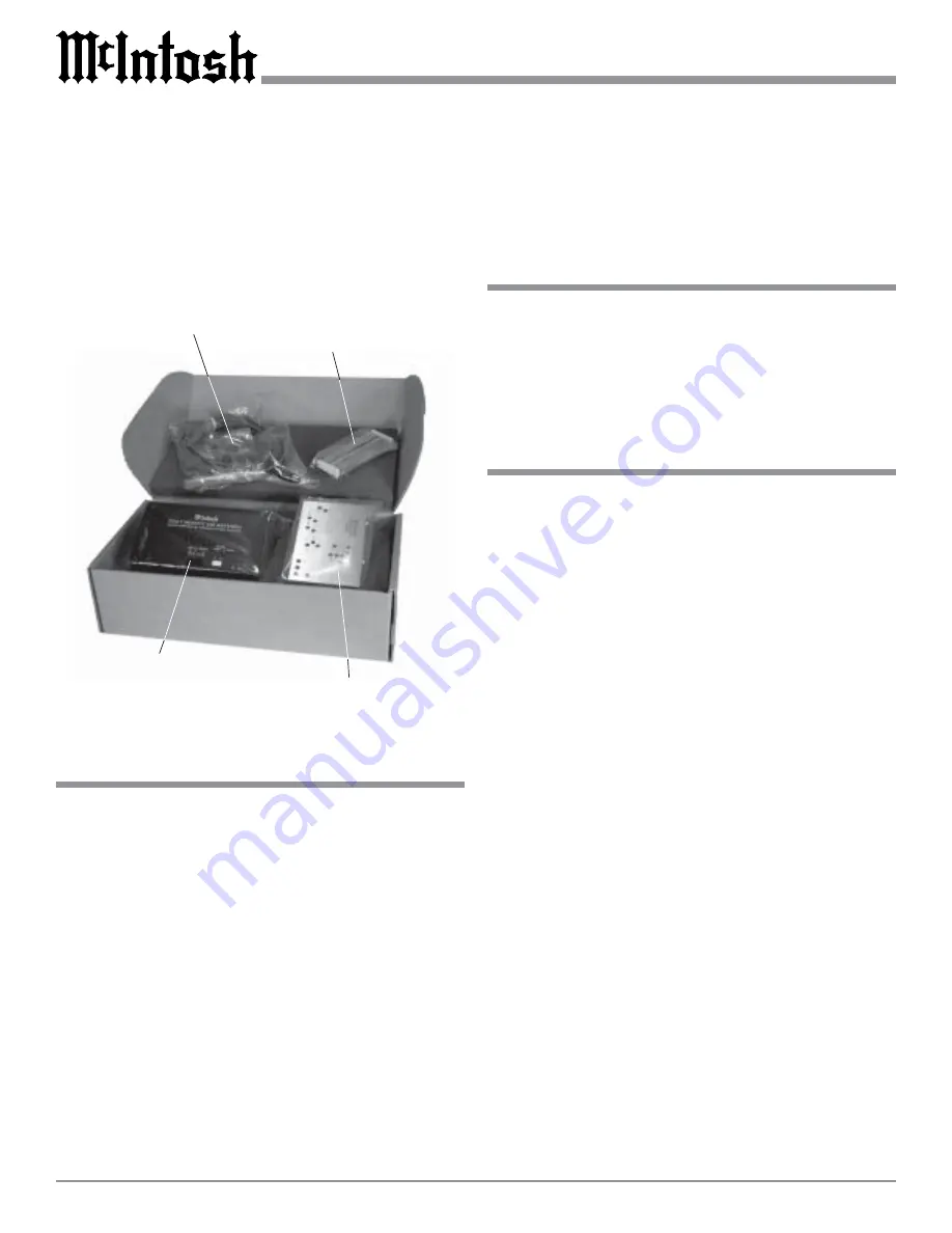
The optional McIntosh TM1 AM/FM Tuner Module can be
added to the MHT200 A/V System Controller for Radio
Broadcast Reception. The TM1 delivers the same excep-
tional performance as the stand-alone McIntosh MR85
Tuner. The TM1 is available from your McIntosh Dealer
and can be installed at any time, usually while you wait.

McIntosh RAA1
Remote AM Antenna

Cable for connecting the
RAA1 to the MHT200

Cables for installing
the McIntosh TM1
AM/FM Tuner Module
into the MHT200

High Performance
McIntosh  AM/FM
Tuner Module

TM1 AM/FM Tuner Module

Performance Features

Introduction

TM1 Table of Contents

Introduction ..................................................................... 58
Performance Features ...................................................... 58
MHT200 Rear and RAA1 Top Panels
Antenna Connections ....................................................... 59
How to Connect Antenna Components ........................... 60
How to Assign Preset Stations ......................................... 61
How to Operate the Tuner ............................................... 63
How to Optimize AM Reception ..................................... 64
FM Specifications ............................................................ 65
AM Specifications ........................................................... 66

www.eskonline.nl

Содержание MHT200

Страница 1: ...hone 607 723 3512 FAX 607 724 0549 A V System Controller Manufactured under license from Dolby Laboratories Dolby Pro Logic and the double D symbol are trademarks of Dolby Laboratories DTS and DTS Digital Surround are registered trademarks of Digital Theater Systems Inc w w w e s k o n l i n e n l ...

Страница 2: ... safety If the provided plug does not fit into your outlet consult an electrician for replacement of the obsolete outlet 10 Protect the power cord from being walked on or pinched particularly at plugs convenience receptacles and the point where they exit from the apparatus 11 Only use attachments accessories specified by the manufacturer 12 Use only with the cart stand tripod bracket or table spec...

Страница 3: ...u at the very top among discriminating music listeners You now have The Best The McIntosh dedication to Quality is assurance that you will receive many years of musical enjoyment from this unit Please take a short time to read the information in this manual We want you to be as familiar as possible with all the features and functions of your new McIntosh Serial Number Purchase Date Dealer Name If ...

Страница 4: ...nt Information 5 Connector Information 6 Introduction 7 Performance Features 7 Dimensions 8 Installation 9 Rear Panel Connections Rear Panel Switch Loudspeaker and Control Connections 10 Rear Panel Audio and Digital Connections 11 Rear Panel Video Connections 12 How to Connect Data and Power Control 13 Loudspeakers 14 Audio and Digital Components 16 Video Components 17 Zone B 18 Front Panel Featur...

Страница 5: ...lso to be connected to the MHT200 10 When an assigned Digital Input and a matching Analog Input are in use the MHT200 automatically searches first for a Digital Signal If no Digital Signal is sensed it switches to the Analog Input 11 Certain DVD or Laser Video Disc Players that are reproducing Digital DTS Signals into a MHT200 Digital Input may only produce noise from their Analog Outputs at the s...

Страница 6: ...plied 5 Pin Terminal Connector Plug Refer to the connection infor mation on the top cover of the RAA1 Power Control Connector The MHT200 s Power Control Outputs provide a 12 volt signal Use a 1 8 inch stereo mini phone plug to connect to the Power Control Input Data and IR Port Connectors The MHT200 s Data Port Output provides Remote Control Signals and the IR Port allows for the connection of oth...

Страница 7: ...00 provides superior eight channel reproduction Dolby Digi tal DTS and discrete Back Surround Decoding combined with complete audio and video switching The McIntosh MHT200 sets new standards for accuracy in a Home The ater System Fully Automatic Channel Level and Time Delay Adjustments The built in test signal generator together with the supplied Calibration Microphone allows for all channels to b...

Страница 8: ...he next page pertaining to installing the MHT200 into cabinets Dimensions 17 3 4 45 09cm 8 7 8 22 54cm Front View of the MHT200 Rear View of the MHT200 9 7 16 23 97cm 13 1 4 33 66cm 17 43 18cm Side View of the MHT200 18 1 2 46 99cm 3 16 0 48cm 13 16 2 06cm 8 1 4 20 96cm 14 1 16 35 72cm 17 43 18cm 7 8 2 22cm w w w e s k o n l i n e n l ...

Страница 9: ...e as set in maintaining all the system com ponents at the coolest possible op erating temperature A custom cabinet installation should provide the follow ing minimum spac ing dimensions for cool operation Al low at least 4 inches 10 16cm above the top 2 inches 5 08cm below the Installation 8 5 16 21 11cm 17 1 16 43 34cm MHT200 Front Panel Custom Cabinet Cutout Cutout Opening for Ventilation Cutout...

Страница 10: ...atible source com ponents to allow remote control operation The SUM Data Port for Zones A and B connects to other McIn tosh Components The HOME Data Port connects to an optional Home Controller RS232 connector for connection to a computer or other control device IR INPUTS for Zone A or B Exter nal Sensors IR POWER On Off Switch for Zone A or B External Sen sors KEYPADS ZONE A and B for a McIntosh ...

Страница 11: ... B Con trol AUDIO INPUTS 1 thru 7 for analog audio signals from a TUNER AUX CD SAT TV DVD VCR1 or VCR2 Components The TUNER Left and Right jacks will provide the Tuner Audio Output Signals when the TM1 AM FM Tuner Module is installed in side the MHT200 DIGITAL OUTPUTS both optical and coaxial provide a digital audio signal to an external digital processor ZONE B PREAMP OUTPUTs provide Left and Rig...

Страница 12: ... Signals to the ZONE A Video Monitor VIDEO OUTPUTS are for supply S Video and Composite Video Signals for recorders VCR 1 and 2 There are also MONitor Zone A S Video and Composite Video Signal Outputs for a monitor TV located in Zone A The MONitor Zone B has a Composite Video Signal Output for monitor TV located in Zone B Note If the MHT200 A V System Controller has the TM1 AM FM Tuner Module inst...

Страница 13: ...o the Home Controller Data In Jack 3 Connect a 4 conductor shielded cable from the MHT200 Zone A Keypad Socket to a McIntosh WK 4 Keypad 4 Connect a Power Control Cable from the MHT200 POWER CONTROL ACC Jack to the McIntosh MVP851 DVD Player Power Control In Jack 5 Connect a Power Control Cable from the McIntosh MVP851 DVD Player Power Control Out Jack to the McIntosh PC 4 Power Control AC Outlet ...

Страница 14: ...inal so the wires cannot slip out and there is no touching of the bare wire or spade lugs between adjacent terminals Refer to figures 4 5 6 How to Connect Loudspeakers Banana plug connection Insert the banana plug into the hole at the top of the terminal Tighten the top portion of the terminal post and the set screw to secure the banana plug in place Note The use of Banana Plugs is for use in the ...

Страница 15: ...enter Front Loudspeaker How to Connect Loudspeakers Left Surround Loudspeaker Back Surround Loudspeaker Right Surround Loudspeaker Right Front Loudspeaker Left Front Loudspeaker w w w e s k o n l i n e n l ...

Страница 16: ...the MVP851 DVD Player 2 Connect a cable from the MHT200 AUDIO INPUTs DVD to the McIntosh 2CH Audio Outputs of the MVP851 DVD Player 3 Connect cables from the MHT200 EIGHT CHANNEL Audio INPUTs to the McIntosh 5 1CH Audio Outputs of the MVP851 DVD Player 4 Connect a cable from the MHT200 SAT Optical DIGI TAL INPUT Input C to the Optical Digital output of a Satellite Receiver 5 Connect a cable from t...

Страница 17: ...Connect video cables from the MHT200 SAT VIDEO INPUTS to the Video Outputs of a Satellite Receiver 4 Connect video cables from the MHT200 COMPO NENT VIDEO 1 INputs to the Video Outputs of a Sat ellite Receiver 5 Connect video cables from the MHT200 VCR1 IN PUTS to the VCR Video Outputs Satellite Receiver To AC Outlet 6 Connect video cables from the MHT200 VCR1 OUT PUTS to the VCR Video Inputs 7 Co...

Страница 18: ...rom the MHT200 MON ZONE B Jack to the Monitor TV Video Input 3 Connect the Loudspeaker Hookup Cables from the MHT200 SPEAKERS Terminals to the Loudspeakers being careful to observe the correct polarities and channel designation Refer to page 14 for information on preparing Loudspeaker Hookup Cables WARNING Loudspeaker terminals are hazardous live and present a risk of electric shock For additional...

Страница 19: ...r Zone A MON ZONE A and MON ZONE B Video Outputs and available for VCR Outputs Adjusts the Listen volume level of all eight channels for Zone A and both channels for Zone B Selects the desired audio operating mode and selects the external eight channel input Low Impedance Dynamic Headphones can be connected for two channel listening The Zone A Loudspeakers are auto matically muted when the head ph...

Страница 20: ...es A and B Press to go into Setup Mode to change the default settings Activates the volume compression circuit supported by selected Dolby Digital sound tracks Switches Zone A On Off and Zone B On Off only if Zone A is already On Switches all AC Power On or Off Front Panel Push buttons and Switch Activates control of Zone B both Input Selection and Volume Adjustment w w w e s k o n l i n e n l ...

Страница 21: ...es when Zone B Control is active Indicates when the Late Night Processing has been selected Indicates when the MHT200 is in Standby On Mode Indicates Input Selection Status Volume Trim Adjustments Surround Modes Setup Functions The Tuner Functions are displayed when the TM1 Tuner Module is installed Indicates the name or type of the Operating Decoding Modes that are in use Indicates when the Input...

Страница 22: ...cIntosh CD Players Mutes the audio Press MODE to switch between various Channel Surround Modes Selects AM Broadcast Band displays current station information and Disc Selection on certain McIntosh CD Players Selects On Screen Func tions for McIntosh DVD Players and certain CD Players Press TRIM then the LEVEL Up or Down to se lect and adjust various functions Selects the Fast Forward Mode on Disc ...

Страница 23: ...adcast band Press and release the Channel Up or Down Push button to move from station to station Press and hold a Channel Up or Down Push button to skip over stations until the push button is released Press RE VIEW to start the automatic brief audition of each of the presets stored in the tuner memory Press REVIEW a sec ond time to stop on a station preset and exit the Review process Note The abov...

Страница 24: ...8 9 Note For normal operation turn the MHT200 On and Off with the Standby On Push button You may also Switch On the MHT200 by simply pressing the Power Push button on the Remote Control If the A V System Controller is not going to be used for an extended period of time turn Off all AC Power with the Power Switch 2 Press and hold the MHT200 Front Panel SETUP Push button for approximately three seco...

Страница 25: ...y LFE1 Level 0dB 33 Sub Filter On 33 1 DD Dolby Digital LFE Low Frequency Effect Sound Information is usually assigned to the Subwoofer Channel If the Subwoofer Channel is switched off and the Front Channel Loudspeakers are set to Large in the Speaker Size Setup Menu the LFE Sound Information will be redirected to the Large Loudspeaker s 5 Exit the MAIN SYSTEM SETUP Menu by pressing the Up or Down...

Страница 26: ...t Front Panel Adjustment Setting Refer to Page Display 8 51 Video Power Control Adjustment Setting Refer to Page Input PowerOn 41 Polarity Positive 41 Delay No 41 Duration Infinite 41 Mode Setup Adjustment Setting Refer to Page PLII Panaorama Off 42 PLII Center Width 3 42 PLII Dimension 0 42 NEO 6 2 42 Music Mode Reverberation 2 42 System Setup for North America Name Settings Refer to Page Video N...

Страница 27: ... this page has been provided to record the settings 4 Select the appropriate Loudspeaker location and type by using the Up or Down directional push buttons to select first the menu item and then press the Left or Right directional push buttons to change the cur rent setting When all of the settings on the SPEAKER SIZE MENU agree with the Loudspeakers in the Sys tem select EXIT on the menu The SPEA...

Страница 28: ...emote Control Refer to figure 14 on page 28 3 Using the Up or Down directional push buttons select Speaker Level on the On Screen Menu followed by the SELECT Push button on the Remote Control Refer to figure 16 4 Adjust the volume of the external test signal by pressing the LEVEL Up or Down Push button on the Re mote Control to a comfortable reference level Note The Left Front Loudspeaker volume l...

Страница 29: ...f the numerical value instead of dB The test signal will start cycling continuously through all Loudspeakers in 3 second intervals 5 While in the Listening Viewing area note the volume levels from each of the Loudspeakers as the test signal switches If you determine that the test signal volume is louder or softer in any of the Loudspeakers the lev els should be adjusted so you hear the same test s...

Страница 30: ... seconds The word SETUP will appear on the Front Panel Display and the MAIN SYS TEM SETUP Menu will appear on the Monitor TV screen Refer to figure 12 on page 25 5 Using the Up or Down directional push buttons select Speaker Setup on the On Screen Menu followed by the SELECT Push button on the Remote Control Refer to figure 16 on page 28 Note It is extremely important to have the room as quiet as ...

Страница 31: ...he Monitor TV screen Refer to figure 12 on page 25 2 Using the Up or Down directional push buttons select Speaker Setup on the On Screen Menu fol lowed by the SELECT Push button on the Remote Control Refer to figure 21 3 Using the Up or Down directional push buttons select Speaker Time Delay on the On Screen Menu followed by the SELECT Push button on the Remote Control Refer to figure 22 SETUP con...

Страница 32: ...n all of the settings on the SPEAKER TIME DE LAY MENU agree with the Loudspeakers in the Sys tem select EXIT on the menu The SPEAKER SETUP Menu will reappear on the Monitor TV screen 7 Continue next to the SUBWOOFER SETTINGS If you do not wish to perform SUBWOOFER SETTINGS ad justments at this time proceed to the next step 8 Select EXIT from the SPEAKER SETUP Menu The MAIN SETUP Menu will reappear...

Страница 33: ...Re fer to figure 13 on page 25 SETUP con t The Subwooofer Settings allow for optimizing perfor mance in the Home Theater System that relate to Room Acoustics and Loudspeaker Characteristics For most Sys tems the default setting will produce the best performance Refer to the Owner s Manual that came with the Loud speaker your Dealer and or the manufacturer of the Loud speaker for recommendations A ...

Страница 34: ...se changes or NO not to save them The MHT200 will then return to normal operation Re fer to figure 13 on page 25 Sub Crossover The MHT200 incorporates a built in Electronic Crossover The Crossover will redirect all of the audio frequencies be low the crossover frequency setting to the Subwoofer and all the frequencies above the setting to the appropriate re maining Home Theater Loudspeakers The de...

Страница 35: ...d subwoofer that has a built in electronic crossover 12 Using the Up or Down directional push buttons select SUB FILTER from the On Screen Menu fol lowed by pressing the Left or Right directional push buttons to switch off the filter Select EXIT on the menu and the SPEAKER SETUP Menu will reappear on the Monitor TV screen 13 Continue to the next SOURCE SETTINGS if you do not wish to perform the re...

Страница 36: ...lowed by the SELECT Push button on the Remote Control 3 Using the Up or Down directional push buttons select SOURCE INPUT from the On Screen Menu followed by pressing the Left or Right directional push buttons to select the desired Input Number Refer to figure 29 Note The first time the SOURCE SETTINGS are accessed the default settings will be indicated Title 4 Using the Up or Down directional pus...

Страница 37: ...t C 4 COMPONENT INPUT 1 5 INPUT LEVEL 6 TRIM PRESETS No Change 7 TRIM PRESET SETUP EXIT inputs can be changed to match up with the two Component Video Sources in the system The following example de scribes how to reassign COMPONENT 1 IN Video Input which by default has been assigned to SAT Input over to the VCR1 Input instead Refer to figure 32 12 Using the Up or Down directional push buttons sele...

Страница 38: ...T Push button to enter the new Input Level for the AUX Input 20 Using the Up or Down directional push buttons select SOURCE INPUT from the On Screen Menu followed by pressing the Left or Right directional push buttons to select the TUNER Input Number 8 Compare the the Tuner Volume Level to the new AUX Input Volume Level 21 If the AUX Input Volume Level is still louder than the Tuner repeat steps 1...

Страница 39: ...wn directional push buttons select TRIM PRESETS on the On Screen Menu 31 Using the Left or Right directional push buttons to select the PRESET Number 1 Note The Trim Preset choices include NO CHANGE FLAT 1 2 3 4 OR 5 32 If there are any additional Source Inputs to have a Trim Preset assigned to it at this time repeat steps 29 through 31 33 Select EXIT on the menu and the MAIN SYSTEM Figure 37 MENU...

Страница 40: ...r Default Input Name New Input Number New Input Name A Optical 1 AUX B Optical 2 CD C Optical 3 SAT D Coaxial 4 TV E Coaxial 5 DVD F Coaxial 6 VCR 1 Digital Audio Source Settings Source Number Default Input Number Default Input Name New Input Number New Input Name 1 IN 3 SAT 2 IN 5 DVD Component Video Source Settings Trim Preset Source Settings Trim Select Preset 1 Preset 2 Preset 3 Preset 4 Prese...

Страница 41: ...on the On Screen Menu followed by pressing the Left or Right directional push but tons to select Positive or Negative going Turn On Sig nal Note All McIntosh Models use a positive going Turn On Signal Delay 5 Using the Up or Down directional push buttons select DELAY on the On Screen Menu followed by pressing the Left or Right directional push buttons to select the desired Turn On Signal Time Dela...

Страница 42: ...ings ranging from 3 to 3 5 Using the Up or Down directional push buttons select PLII DIMENSION on the On Screen Menu fol lowed by pressing the Left or Right directional push buttons to select the desired effect NEO 6 Center Image This mode takes some of the center channel signal and adds it to the left and right front Loudspeakers thus in creasing the width of the front sound field The effect can ...

Страница 43: ...ssing Left or Right directional push buttons to select either OFF SIMPLE or FULL On SCREEN Display Information The SIMPLE On SCREEN Display Information will include Zone A In put Selection and Volume The FULL On SCREEN Display Information will in clude the SIMPLE Display Information for Zone A plus additional Audio Video Input Information OSD Routing This setting selects which video output Composi...

Страница 44: ...the first 4 If possible first write down any current Setup Settings and Tuner Presets before proceeding as all settings will be returned to factory default condition Press the POWER switch to ON the Red LED above the STANDBY ON Push button lights to indicate the MHT200 is in Standby mode Press the STANDBY ON Push button then immediately press and hold in the SETUP Push button before the title of M...

Страница 45: ... make changes to the factory default settings refer to the SETUP Section of this Owner s Manual Power On and Off Press the POWER switch to ON and the Red LED above the STANDBY ON Push button illuminates to indicate the MHT200 is in Standby Mode Switch On the MHT200 by pressing the STANDBY ON Push button The title MHT200 will appear on the Front Panel Alphanumeric Display for approximately two seco...

Страница 46: ... pressing the ZONE B Push button Refer to How to Operate Zone B on page 54 Tune If the optional TM1 Tuner Module is installed into the MHT200 Preset AM FM Radio Stations may be selected by rotating the TRIM SELECT Control to the TUNE Posi tion and then press the TUNE Up or Down Push but tons Refer to page 64 for additional information Late Night The LATE NIGHT Push button turns a volume compres si...

Страница 47: ...axial 5 Mode Cinema 1 VIDEO Signal SVideo NTSC Input SVideo 5 54 Selected Input Audio Input Signal is Dolby Digital 5 1 Digital Input Selected is Number 5 Letter E Surround Mode is set to Cinema 1 Video Input Signal is S Video and in the NTSC Video Format Video Input Selected is Number 5 Slide Bar to display relative volume setting Indicates the current volume setting Figure 46 AM FM Broadcast or ...

Страница 48: ... Control and the Preset Label will appear on the bottom of the On Screen Display The Frequency of the Station will appear when using the Channel Up and Down Push buttons The On Screen Display will also indicate the TRIM MODE adjustments of either the Channel Levels or Tone settings Refer to figure 46 on the previous page and figure 47 Figure 47 Center 3dB Trim Mode Adjustment Trim Mode Level w w w...

Страница 49: ... 50 Note The INPUT Selector Switch will return to ZONE A Input Selection about five seconds after the ZONE B Push button is pressed and the INPUT Selector is no longer being rotated 3 Adjust the record level using the recorder s volume control How To Make A Recording How to Operate the MHT200 con t Figure 49 Figure 48 4 To monitor the tape during the recording process with a three head tape record...

Страница 50: ...right of SUB TRIM on the Front Panel Display This is an example of increasing the Subwoofer level by 5dB 3 Press and release the TRIM Push button until SURR TRIM appears on the front panel display Refer to fig ure 54 4 Press the LEVEL Down Push button until the 10 appears to the right of SURR TRIM on the Front Panel Display This is an example of decreasing the Surround Loudspeakers Levels by 10dB ...

Страница 51: ...llows adjustments to the brightness of the Front Panel Alphanumeric Display to the desired intensity The Display Trim brightness range ex tends from Off to a maximum of 10 Note You may find it easiest to make Display adjustments with the Front Panel Controls How to Operate the MHT200 con t Figure 59 1 Press and release the TRIM Push button on the Remote Control or rotate the TRIM SELECT Control un...

Страница 52: ...numeric Display will indicate MU SIC 1 Refer to figure 62 and 70 This Mode utilizes Dolby Pro Logic II Processing to create a wide and deep sound space The effect may be varied depending upon the set tings for Dolby Pro Logic II Refer to How to change Mode Setup on page 42 to alter the settings Figure 60 Figure 62 Figure 63 Figure 64 Figure 61 Music 2 The Front Panel Alphanumeric Display will indi...

Страница 53: ...his provides DTS NEO 6 processing Analog Signals and 2 Channel Digital Signals It also decodes Dolby Digital EX or DTS ES Signals External The Front Panel Alphanumeric Display indicates EXTER NAL Refer to figures 68 and 70 All internal signal pro cessing is bypassed and the eight Rear Panel EXTERNAL INPUTS are activated so the MHT200 performs as an eight channel preamplifier for an external source...

Страница 54: ...ush button is illuminated approximately three seconds the Zone B Input Source and Volume Levels may be changed using the Front Panel INPUT and VOLUME Controls The Zone B Power may also be switched Off by pressing the Front Panel STANDBY ON Push button within the three second time period If Front Panel Control reverts back to Zone A the LED Indicator above the ZONE B Push button is not illuminated ...

Страница 55: ...ntrolling a Source Component from Zone B To control a source component from the Keypad or Sensor perform the following steps Refer to figures 75 and or 76 1 Press the appropriate source push button e g CD on the Keypad or Remote Control and immediately press the appropriate control push button for the desired function e g the Next Push button to play the next selection from the disc Note It is nec...

Страница 56: ...ll channels Sensitivity Analog Input 100mV IHF Dolby Level 200mV Input External Input 200mV for 2 0V output Signal To Noise Ratio Greater than 90dB A weighted Maximum Input Signal Analog Input 6Vrms Tone Controls 12dB from the flat setting 1 If any of the Channels have the Loudspeaker Setting of Small the subwoofer has an electronic low pass filter with a 24dB per Octave rolloff in all modes excep...

Страница 57: ...atts 6 x 80 watts Rated Power Band 20Hz to 20 000Hz into a 4 ohm load 2 x 150 watts 6 x 100 watts Rated Power Band 20Hz to 20 000Hz into a 8 ohm load 2 x 95 watts 6 x 75 watts Minimum sine wave continuous average power output per channel for Zone B with both channels operating is Rated Power Band 20Hz to 20 000Hz into a 4 ohm load 2 x 150 watts Rated Power Band 20Hz to 20 000Hz into a 8 ohm load 2...

Страница 58: ...ned Off Alphanumeric Fluorescent Display The MHT200 Multi function Front Panel Display indicates station frequency station preset number signal strength stereo and broadcast band The optional McIntosh TM1 AM FM Tuner Module can be added to the MHT200 A V System Controller for Radio Broadcast Reception The TM1 delivers the same excep tional performance as the stand alone McIntosh MR85 Tuner The TM1...

Страница 59: ...ects to an external FM antenna or cable AM ANT An tenna connector allows a McIntosh Remote Antenna to be connected RAA1 Remote Antenna can be adjusted to a position for optimum reception of your fa vorite AM stations Connects with supplied cable to the MHT200 w w w e s k o n l i n e n l ...

Страница 60: ...cket on the back panel of the MHT200 Note If a longer length cable needs to be used between the MHT200 and the RAA1 use a 2 conductor shielded cable Refer to page 6 for additional connection information 2 Connect a 75 ohm coax cable from an FM antenna or cable system to the MHT200 75 ohm FM ANT con nector How to Connect Antenna Components w w w e s k o n l i n e n l ...

Страница 61: ... and then to AM Presets 1 to 9 Tuning Mode The entering of stations into Preset Memory in MHT200 may be performed by either Automatic Search for available station or Manual Tuning the dial for them 4 Using the Up or Down directional push buttons select TUNE MODE from the On Screen Menu fol lowed by pressing the Left or Right directional push buttons to select AUTOmatic or MANUAL Re fer to figure 7...

Страница 62: ...een entered press the Left or Right directional push buttons or press the SELECT Push button until the TUNER PRESET Menu displays an arrow in front of PRESET AS SIGNED Preset Assigned 11 Using Up or Down directional push buttons select PRESET ASSIGNED from the On Screen Menu fol lowed by pressing the Left or Right directional push buttons to select Yes or No If No is selected the MHT200 will skip ...

Страница 63: ... TUNER PRESETS 1 PRESET FM1 2 TUNING MODE Auto 3 FREQUENCY 91 50 MHz 4 LABEL KABC EXIT Figure 83 MENU TUNER PRESETS 1 PRESET FM1 2 TUNING MODE Auto 3 FREQUENCY 91 50 MHz 4 LABEL KABC 5 PRESET ASSIGNED Yes EXIT w w w e s k o n l i n e n l ...

Страница 64: ...ime the FM or AM Push button is pressed the Front Panel Alphanumeric will display Signal Strength Stereo Mono for FM Broadcasts only and the default Preset Name or the Custom Entered How to Operate the Tuner Figure 86 Figure 84 Figure 87 Preset Name Refer to figure 84 The second time the FM or AM Push button is pressed the Front Panel Alphanumeric will display the Signal Strength Stereo Mono for F...

Страница 65: ...mer L1 for maximum signal strength Refer to figure 88 2 Tune to a weak AM station near 1400kHz on the AM band Using an appropriate NON METAL LIC tool adjust the 1400kHz Trimmer Capaci tor C1 for maxi mum signal strength Refer to figure 88 3 Repeat steps 1 and 2 until no further improvements can be obtained Preset Number Frequency City Call Letters Name FM 1 FM 2 FM 3 FM 4 FM 5 FM 6 FM 7 FM 8 FM 9 ...

Страница 66: ...ermodulation Distortion Mono 0 25 Stereo 0 45 Capture Ratio 1 2dB Alternate Channel Selectivity 75dB Spurious Response 100dB Image Response 75dB RF Intermodulation 65dB Stereo Separation 45dB at 100Hz 45dB at 1 000Hz 35dB at 10 000Hz SCA Rejection 65dB TM1 FM and AM Specifications AM Tuner Specifications Sensitivity 20uV External Antenna Input Signal To Noise Ratio 48dB at 30 modulation 58dB at 10...

Страница 67: ...shipment the equipment must be packed exactly as shown below It is very important that the four plastic feet are at tached to the bottom of the equipment Two 10 x 2 1 4 inch screws and washers must be used to fasten the unit securely to the bottom pad and shipping skid This will en sure the proper equipment location on the bottom pad Fail ure to do this will result in shipping damage Use the origi...

Страница 68: ...t Binghamton NY 13903 The continuous improvement of its products is the policy of McIntosh Laboratory Incorporated who reserve the right to improve design without notice Printed in the U S A McIntosh Part No 040860 w w w e s k o n l i n e n l ...

Отзывы: